
After years of faithful service, the probe on my kitchen thermometer was starting to fail. I have a spare, so the failing one went in a drawer. The other day I was thinking about making my own temperature probe for another project, and figured now would be a perfect time to cut open that old probe to see what’s inside!
Components

I took the probe down to the ‘ol hackerspace and gave it quick cut on the bandsaw. With the outer sheath open everything just slid out, and I got a look at the internals:
- Thermistor
- plastic sheath
- shielded/insulated single conductor wire
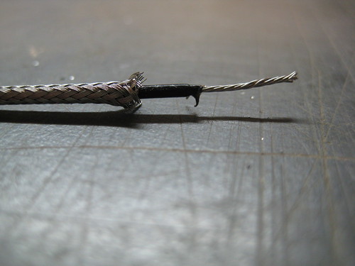
That last one threw me for a loop. A SINGLE conductor wire? I thought for sure there would be two insulated conductors inside that shielding.  It turns out they actually use the shielding as one of the conductors. In the picture below you can see where the negative lead (I presume) is attached to the shield.

So there you have it.  Current travels out through the insulated wire, and returns through the shield. The resistance of the loop is determined by the temperature the thermistor is seeing. The base unit infers the temperature and displays it.
You Mentioned “Another Project?”
Oh right, this is a project blog. The idea for a probe project is this: I make barbecue. During the ~16 hour cooking process I’d like to have 4-5 probes in the meat at various depths. In this way I could show the temperature gradient throughout the cooking process. If I make my own, the probes would be cheap enough to make this project feasible.
Pingback: Problems with thermometer – YAY! | Coffee Spot