
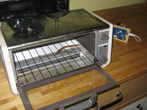
Pic 1: Arduino Controlled Toaster-Oven. No, I have not tried making toast with it
The Mark 1 reflow toaster is complete! (“Mark 1” is another way of saying there’s a lot of work to be done.)
It can hold +/- 1 °F, which should be sufficient for surface mount electronics. I say “should be” because I haven’t soldered anything with it yet.
Construction:
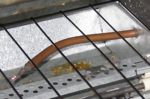
Pic 2: Termistor support mast
Temperature sensing is done by a thermistor. Simple solder connections and 20ga wire get the signal back to the Arduino. (UPDATE: the thermistor is wired at the Arduino using this method.) The wires are run through a copper tube, and everything is held in place with JB weld. This setup seems to work, even at temperatures that melt solder. I don’t know if that’s because the JB keeps the solder connections from melting, or if it holds the molten solder in place during run-time. Either way, I haven’t had any problems getting temperature readings.
On the heat side, an SSR is spliced directly into the 120V plug wire. This is not safe. The SSR is fine, but having exposed 120V dangling near the toaster is a recipe for bad times. In the mark 2 that will all be neatly enclosed.
The toaster’s intrinsic temperature control was left in place, turned all the way up to 500°F. If everything is working correctly, it will stay out of the way. If something goes wrong, the temperature will be prevented from rising without bound.
Temperature Control:
I decided to use the Arduino PID Library to control the oven temperature. I think it works really well, but I’m a little biased.
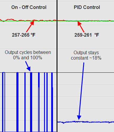
Pic 3: Temperature control: On-Off vs PID. On-Off is easier, while PID provides tighter control with a more stable output
The easiest way to control temperature would be to use on-off control: “If I’m too cold, turn on. if I’m too hot, turn off.” I tried that first. As you can see in the picture above, it does a decent job. The oven temperature (red line) stays within 5 °F of where we want to be (green line.) This is probably fine in this application. The one questionable thing is the output. Since it’s cycling between full on and full off, there might be some extra thermal shock to the system.
On-Off control is probably fine, but as I said, I’m biased. I decided to implement pid control. As you can see, it does a better job of staying where we want to be. Instead of 5 degrees, now the temperature stays within 1 degree. Also, since the output is essentially constant, there’s a better chance that there will be a uniform temperature gradient in the oven.
The extra effort probably wasn’t necessary, but I still think it’s pretty cool.
Next Steps
- I think the termistor may be in a bad location. I wanted it to be really close to the workpiece, so I put it directly underneath where the workpiece would go. it seems that when there’s a piece in place, it actually changes how heat flows in that area, and the temperature reading is almost 20 degrees higher. I’ll need to see if this adversely impacts reflow… once I actually reflow something.
- I may need to upgrade to a convection toaster to get more uniform temperature distribution
- currently I’m adjusting setpoints and watching progress using the PID frontend. it would be nice to move that functionality onto the arduino. maybe an LCD and some buttons…
- It might be cool to have a pre-programmed setpoint profile that the oven can cycle through
Nice job with the reflow oven. I wonder if you could hack / create an IR temp sensor to give you a surface temp of the piece being reflowed..?
that would be an interesting thing to bring into the mix. It might be tricky to control using IR as an input, but at the very least it would be neat to use for indication.
Pardon my weak analog electronics knowledge, but how are you limiting the amount of power that you supply to the heating elements? The On-Off vs. PID graph above shows you providing 18% power output, yet the text says you’re using an SSR. Is there way of controlling an SSR besides having it operate as a simple on/off switch? Or do you have a transister inline after the SSR?
Keep up the great posts, they’re very interesting for someone who’s getting into electronics!
Fair question trevor. Strictly speaking, the SSR is always either on or off. In the pid graph, I’m using the pwm output of the arduino, which cycles at 50ms (I think.) This is so fast that from the heater’s perspective it might as well be 18%. sorry for the confusion.
Hello,
By any chance, would you be willing to share some code/schematics
Thanks