In the previous post I spent all my time explaining the benefits of Proportional on Measurement. In this post I’ll explain the code. People seemed to appreciate the step-by-step way I explained things last time, so that’s what I’ll do here. The 3 passes below detail how I went about adding PonM to the PID library.
First Pass – Initial Input and Proportional-Mode selection
/*working variables*/
unsigned long lastTime;
double Input, Output, Setpoint;
double ITerm, lastInput;
double kp, ki, kd;
int SampleTime = 1000; //1 sec
double outMin, outMax;
bool inAuto = false;

#define MANUAL 0
#define AUTOMATIC 1

#define DIRECT 0
#define REVERSE 1
int controllerDirection = DIRECT;

#define P_ON_M 0
#define P_ON_E 1
bool pOnE = true;
double initInput;

void Compute()
{
   if(!inAuto) return;
   unsigned long now = millis();
   int timeChange = (now - lastTime);
   if(timeChange>=SampleTime)
   {
      /*Compute all the working error variables*/
      double error = Setpoint - Input;
      ITerm+= (ki * error);
      if(ITerm > outMax) ITerm= outMax;
      else if(ITerm < outMin) ITerm= outMin;
      double dInput = (Input - lastInput);

      /*Compute P-Term*/
      if(pOnE) Output = kp * error;
      else Output = -kp * (Input-initInput);

      /*Compute Rest of PID Output*/
      Output += ITerm - kd * dInput;
      if(Output > outMax) Output = outMax;
      else if(Output < outMin) Output = outMin;

      /*Remember some variables for next time*/
      lastInput = Input;
      lastTime = now;
   }
}

void SetTunings(double Kp, double Ki, double Kd, int pOn)
{
   if (Kp<0 || Ki<0|| Kd<0) return;

   pOnE = pOn == P_ON_E;

   double SampleTimeInSec = ((double)SampleTime)/1000;
   kp = Kp;
   ki = Ki * SampleTimeInSec;
   kd = Kd / SampleTimeInSec;

  if(controllerDirection ==REVERSE)
   {
      kp = (0 - kp);
      ki = (0 - ki);
      kd = (0 - kd);
   }
}

void SetSampleTime(int NewSampleTime)
{
   if (NewSampleTime > 0)
   {
      double ratio  = (double)NewSampleTime
                      / (double)SampleTime;
      ki *= ratio;
      kd /= ratio;
      SampleTime = (unsigned long)NewSampleTime;
   }
}

void SetOutputLimits(double Min, double Max)
{
   if(Min > Max) return;
   outMin = Min;
   outMax = Max;

   if(Output > outMax) Output = outMax;
   else if(Output < outMin) Output = outMin;

   if(ITerm > outMax) ITerm= outMax;
   else if(ITerm < outMin) ITerm= outMin;
}

void SetMode(int Mode)
{
    bool newAuto = (Mode == AUTOMATIC);
    if(newAuto == !inAuto)
    {  /*we just went from manual to auto*/
        Initialize();
    }
    inAuto = newAuto;
}

void Initialize()
{
   lastInput = Input;
   initInput = Input;
   ITerm = Output;
   if(ITerm > outMax) ITerm= outMax;
   else if(ITerm < outMin) ITerm= outMin;
}

void SetControllerDirection(int Direction)
{
   controllerDirection = Direction;
}
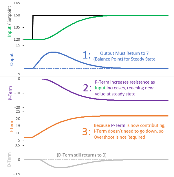
Proportional on Measurement provides increasing resistance as the input changes, but without a frame of reference our performance would be a little wonky. If the PID Input is 10000 when we first turn on the controller, do we really want to start resisting with Kp*10000? No. We want to use our initial input as a reference point (line 108,) the increase or decrease resistance as the input changes from there (line 38.)
The other thing we need to do is allow the user to select whether they want to do Proportional on Error or Measurement. After the last post it might seem like PonE is useless, but it’s important to remember that for many loops it works well. As such, we need to let the user choose which mode they want (lines 51&55) and then act accordingly in the calculation (lines 37&38).
Second Pass – On-the-fly tuning changes
While the code above does indeed work, it has a problem that we’ve seen before. When tuning parameters are changed at runtime, we get an undesirable blip.
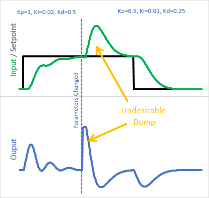
Why is this happening?
The last time we saw this, it was that the integral was being rescaled by a new Ki. This time, it’s that (Input – initInput) is being rescaled by Kp. the solution I chose is similar to what I did for Ki: instead of treating the Input – initInput as a monolithic unit multiplied by the current Kp, I broke it into individual steps multiplied by the Kp at that time:
![]()
/*working variables*/
unsigned long lastTime;
double Input, Output, Setpoint;
double ITerm, lastInput;
double kp, ki, kd;
int SampleTime = 1000; //1 sec
double outMin, outMax;
bool inAuto = false;

#define MANUAL 0
#define AUTOMATIC 1

#define DIRECT 0
#define REVERSE 1
int controllerDirection = DIRECT;

#define P_ON_M 0
#define P_ON_E 1
bool pOnE = true;
double PTerm;

void Compute()
{
   if(!inAuto) return;
   unsigned long now = millis();
   int timeChange = (now - lastTime);
   if(timeChange>=SampleTime)
   {

      /*Compute all the working error variables*/
      double error = Setpoint - Input;
      ITerm+= (ki * error);
      if(ITerm > outMax) ITerm= outMax;
      else if(ITerm < outMin) ITerm= outMin;
      double dInput = (Input - lastInput);

   	  /*Compute P-Term*/
   	  if(pOnE) Output = kp * error;
   	  else
   	  {
   	     PTerm -= kp * dInput;
   	     Output = PTerm;
   	  }

   	  /*Compute Rest of PID Output*/
   	  Output += ITerm - kd * dInput;

      if(Output > outMax) Output = outMax;
      else if(Output < outMin) Output = outMin;

      /*Remember some variables for next time*/
      lastInput = Input;
      lastTime = now;
   }
}

void SetTunings(double Kp, double Ki, double Kd, int pOn)
{
   if (Kp<0 || Ki<0|| Kd<0) return;

   pOnE = pOn == P_ON_E;

   double SampleTimeInSec = ((double)SampleTime)/1000;
   kp = Kp;
   ki = Ki * SampleTimeInSec;
   kd = Kd / SampleTimeInSec;

  if(controllerDirection ==REVERSE)
   {
      kp = (0 - kp);
      ki = (0 - ki);
      kd = (0 - kd);
   }
}

void SetSampleTime(int NewSampleTime)
{
   if (NewSampleTime > 0)
   {
      double ratio  = (double)NewSampleTime
                      / (double)SampleTime;
      ki *= ratio;
      kd /= ratio;
      SampleTime = (unsigned long)NewSampleTime;
   }
}

void SetOutputLimits(double Min, double Max)
{
   if(Min > Max) return;
   outMin = Min;
   outMax = Max;

   if(Output > outMax) Output = outMax;
   else if(Output < outMin) Output = outMin;

   if(ITerm > outMax) ITerm= outMax;
   else if(ITerm < outMin) ITerm= outMin;
}

void SetMode(int Mode)
{
    bool newAuto = (Mode == AUTOMATIC);
    if(newAuto == !inAuto)
    {  /*we just went from manual to auto*/
        Initialize();
    }
    inAuto = newAuto;
}

void Initialize()
{
   lastInput = Input;
   PTerm = 0;
   ITerm = Output;
   if(ITerm > outMax) ITerm= outMax;
   else if(ITerm < outMin) ITerm= outMin;
}

void SetControllerDirection(int Direction)
{
   controllerDirection = Direction;
}
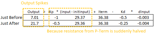
Instead of multiplying the entirety of Input-initInput by Kp, we now keep a working sum, PTerm. At each step we multiply just the current input change by Kp and subtract it from PTerm (line 41.) Here we can see the impact of the change:
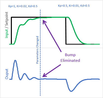
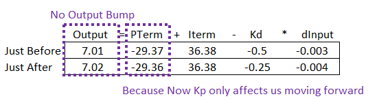
Because the old Kps are “in the bank”, the change in tuning parameters only affects us moving forward
Final Pass – Sum problems.
I won’t go into complete detail (fancy trends etc) as to what wrong with the above code. It’s pretty good, but there are still major issues with it. For example:
- Windup, sort of: While the final output is limited between outMin and outMax, it’s possible for PTerm to grow when it shouldn’t. It wouldn’t be as bad as integral windup, but it still wouldn’t be acceptable
- On-the-fly changes: If the user were to change from P_ON_M to P_ON_E while running, then after some time return back, PTerm wouldn’t be property initialized and it would cause an output bump
There are more, but just these are enough to see what the real issue is. We’ve dealt with all of these before, back when we created ITerm. Rather than go through and re-implement the same solutions for PTerm, I decided on a more aesthetically-pleasing solution.
By merging PTerm and ITerm into a single variable called “outputSum”, the P_ON_M code then benefits from the all the ITerm fixes that are already in place, and because there aren’t two sums in the code there isn’t needless redundancy.
/*working variables*/
unsigned long lastTime;
double Input, Output, Setpoint;
double outputSum, lastInput;
double kp, ki, kd;
int SampleTime = 1000; //1 sec
double outMin, outMax;
bool inAuto = false;

#define MANUAL 0
#define AUTOMATIC 1

#define DIRECT 0
#define REVERSE 1
int controllerDirection = DIRECT;

#define P_ON_M 0
#define P_ON_E 1
bool pOnE = true;


void Compute()
{
   if(!inAuto) return;
   unsigned long now = millis();
   int timeChange = (now - lastTime);
   if(timeChange>=SampleTime)
   {

      /*Compute all the working error variables*/
      double error = Setpoint - Input;
      double dInput = (Input - lastInput);
      outputSum+= (ki * error);

	  /*Add Proportional on Measurement, if P_ON_M is specified*/
	  if(!pOnE) outputSum-= kp * dInput

      if(outputSum > outMax) outputSum= outMax;
      else if(outputSum < outMin) outputSum= outMin;

   	  /*Add Proportional on Error, if P_ON_E is specified*/
	  if(pOnE) Output = kp * error;
	  else Output = 0;

   	  /*Compute Rest of PID Output*/
   	  Output += outputSum - kd * dInput;

      if(Output > outMax) Output = outMax;
      else if(Output < outMin) Output = outMin;

      /*Remember some variables for next time*/
      lastInput = Input;
      lastTime = now;
   }
}

void SetTunings(double Kp, double Ki, double Kd, int pOn)
{
   if (Kp<0 || Ki<0|| Kd<0) return;

   pOnE = pOn == P_ON_E;

   double SampleTimeInSec = ((double)SampleTime)/1000;
   kp = Kp;
   ki = Ki * SampleTimeInSec;
   kd = Kd / SampleTimeInSec;

  if(controllerDirection ==REVERSE)
   {
      kp = (0 - kp);
      ki = (0 - ki);
      kd = (0 - kd);
   }
}

void SetSampleTime(int NewSampleTime)
{
   if (NewSampleTime > 0)
   {
      double ratio  = (double)NewSampleTime
                      / (double)SampleTime;
      ki *= ratio;
      kd /= ratio;
      SampleTime = (unsigned long)NewSampleTime;
   }
}

void SetOutputLimits(double Min, double Max)
{
   if(Min > Max) return;
   outMin = Min;
   outMax = Max;

   if(Output > outMax) Output = outMax;
   else if(Output < outMin) Output = outMin;

   if(outputSum > outMax) outputSum= outMax;
   else if(outputSum < outMin) outputSum= outMin;
}

void SetMode(int Mode)
{
    bool newAuto = (Mode == AUTOMATIC);
    if(newAuto == !inAuto)
    {  /*we just went from manual to auto*/
        Initialize();
    }
    inAuto = newAuto;
}

void Initialize()
{
   lastInput = Input;

   outputSum = Output;
   if(outputSum > outMax) outputSum= outMax;
   else if(outputSum < outMin) outputSum= outMin;
}

void SetControllerDirection(int Direction)
{
   controllerDirection = Direction;
}
And there you have it. The above functionality is what is now present in v1.2.0 of the Arduino PID.
But wait, there’s more: Setpoint Weighting.
I didn’t add the following to the Arduino library code, but this is a feature that might be of some interest if you want to roll your own. Setpoint Weighting is, at it’s core, a way to have both PonE and PonM at the same time. By specifying a ratio between 0 and 1, you can have 100% PonM, 100% PonE (respectively) or some ratio in between. This can be helpful if you have a process that’s not perfectly integrating (like a reflow oven) and want to account for this.
Ultimately I decided not to add it to the library at this time, as it winds up being ANOTHER parameter to adjust/explain, and I didn’t think the resulting benefit was worth it. At any rate, here is the code if you’d like to modify the code to have Setpoint Weighting instead of just pure PonM/PonE selection:
/*working variables*/
unsigned long lastTime;
double Input, Output, Setpoint;
double outputSum, lastInput;
double kp, ki, kd;
int SampleTime = 1000; //1 sec
double outMin, outMax;
bool inAuto = false;

#define MANUAL 0
#define AUTOMATIC 1

#define DIRECT 0
#define REVERSE 1
int controllerDirection = DIRECT;

#define P_ON_M 0
#define P_ON_E 1
bool pOnE = true, pOnM = false;
double pOnEKp, pOnMKp;


void Compute()
{
   if(!inAuto) return;
   unsigned long now = millis();
   int timeChange = (now - lastTime);
   if(timeChange>=SampleTime)
   {

      /*Compute all the working error variables*/
      double error = Setpoint - Input;
      double dInput = (Input - lastInput);
      outputSum+= (ki * error);

	  /*Add Proportional on Measurement, if P_ON_M is specified*/
	  if(pOnM) outputSum-= pOnMKp * dInput

      if(outputSum > outMax) outputSum= outMax;
      else if(outputSum < outMin) outputSum= outMin;

   	  /*Add Proportional on Error, if P_ON_E is specified*/
	  if(pOnE) Output = pOnEKp * error;
	  else Output = 0;

   	  /*Compute Rest of PID Output*/
   	  Output += outputSum - kd * dInput;

      if(Output > outMax) Output = outMax;
      else if(Output < outMin) Output = outMin;

      /*Remember some variables for next time*/
      lastInput = Input;
      lastTime = now;
   }
}

void SetTunings(double Kp, double Ki, double Kd, double pOn)
{
   if (Kp<0 || Ki<0|| Kd<0 || pOn<0 || pOn>1) return;

   pOnE = pOn>0; //some p on error is desired;
   pOnM = pOn<1; //some p on measurement is desired;

   double SampleTimeInSec = ((double)SampleTime)/1000;
   kp = Kp;
   ki = Ki * SampleTimeInSec;
   kd = Kd / SampleTimeInSec;

  if(controllerDirection ==REVERSE)
   {
      kp = (0 - kp);
      ki = (0 - ki);
      kd = (0 - kd);
   }

   pOnEKp = pOn * kp;
   pOnMKp = (1 - pOn) * kp;
}

void SetSampleTime(int NewSampleTime)
{
   if (NewSampleTime > 0)
   {
      double ratio  = (double)NewSampleTime
                      / (double)SampleTime;
      ki *= ratio;
      kd /= ratio;
      SampleTime = (unsigned long)NewSampleTime;
   }
}

void SetOutputLimits(double Min, double Max)
{
   if(Min > Max) return;
   outMin = Min;
   outMax = Max;

   if(Output > outMax) Output = outMax;
   else if(Output < outMin) Output = outMin;

   if(outputSum > outMax) outputSum= outMax;
   else if(outputSum < outMin) outputSum= outMin;
}

void SetMode(int Mode)
{
    bool newAuto = (Mode == AUTOMATIC);
    if(newAuto == !inAuto)
    {  /*we just went from manual to auto*/
        Initialize();
    }
    inAuto = newAuto;
}

void Initialize()
{
   lastInput = Input;
   outputSum = Output;
   if(outputSum > outMax) outputSum= outMax;
   else if(outputSum < outMin) outputSum= outMin;
}

void SetControllerDirection(int Direction)
{
   controllerDirection = Direction;
}
Instead of setting pOn as an integer, it now comes in as a double which allows for a ratio (line 58.) In addition to some flags (lines 62&63) weighted Kp terms are computed on lines 77-78. Then on lines 37 and 43 the weighted PonM and PonE contributions are added to the overall PID output.