Archive for the ‘Electronic’ Category

Introducing the osPID

Tuesday, January 3rd, 2012

About 5 months ago I sent an out-of-the-blue email to RocketScream electronics asking if they wanted to help me build an open source PID controller. It’s been far more challenging than I expected, but today I get to announce the release of my first open source hardware project: the osPID!

(pause for applause)

(more…)

flattr this!

When a Maker Gets Married

Monday, August 15th, 2011


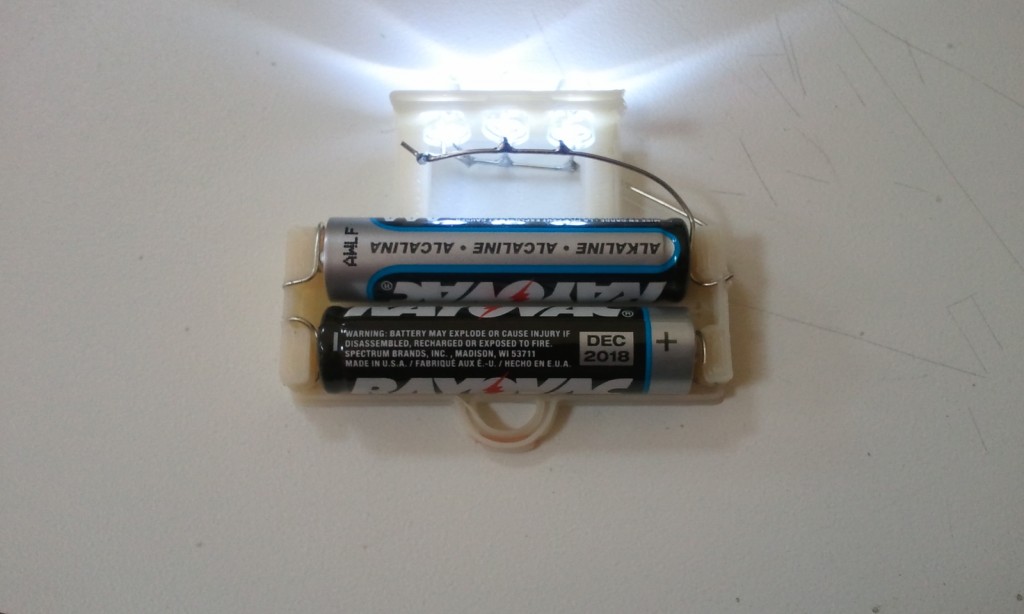
I got married a couple of weeks ago. We did all the planning / decoration ourselves. By we, or course, I mean my wife. One of the things she wanted to do was have paper lanterns suspended above the tables.

The initial plan was to use throwies, but I felt they wouldn’t give as much light as a commercial 3 LED solution. This led me to a fun, albeit time consuming project.
(more…)

flattr this!

Arduino Uno Keeps Header Offset

Monday, September 27th, 2010

Uno Spacing

The newest version of the arduino was announced last week. At first glance it seemed as though they got rid of the offset header spacing, but a closer look at the spec showed that it is still 0.16 inches. It would have been a bold move to change that spacing; there are a lot of 0.16-spaced shields out there. Looks like Sparkfun will be selling offset headers for some time to come.

See also: Offset Header Explained

flattr this!

This changes everything

Friday, August 13th, 2010

A lot of my projects involve 120VAC, switching relatively slowly. Most people use mechanical relays in that situation, but I don’t like them; I try to avoid moving parts whenever possible. Up to this point, I’ve always used solid state relays. They work really well, but they’re expensive. What this means is that I’ve needed to move my same 2 SSRs from project to project, which is kind of a pain.

Well no more! Enter the humble Triac. They’re tiny, cheap, and in my slow switching applications the circuitry isn’t too complicated. That being said, it’s still the most complicated circuit I’ve ever attempted.

triac schematic

I figured a good first application would be a switched outlet. It’s fairly simple, and it’s something that I could use in prototyping later on.

IMG_8431

IMG_8430

And there you have it. A neat little package with two independently controlled power plugs. The best part is the cost. The whole thing cost less then $10! With SSRs it would have been ~$80, and I don’t know if they even would have fit in the box.

Triac Box from br3ttb on Vimeo.

There’s one issue I’m going to need to keep an eye on. Apparently, if a Triac overheats, it tends to fail into the on position. There’s nothing here that detects if this is about to happen, so I’ll have to keep an eye on it for a while to be sure there’s adequate cooling

Update: There is NOT adequate cooling. I did a real test just now. 1500W toaster oven on high. after a minute I started smelling perfboard. Everything was disconnected before any damage was done, but some design revisions are in order before I try to switch high loads again.

flattr this!

Success!

Saturday, October 10th, 2009

chugging along

Constant Air + Constant Heat = Constant Smoke. Who knew?

Constant Air

pre-patch JBpost-patch

Holes. There were tons of holes. To have complete control over the air I had to patch them all. Most of them were fairly easy. A little JBWeld and aluminum foil and I had rigid, (fairly) high temp patches. All the seams got a bead of JB for good measure as well.

repositioned ramp

The biggest hole of all was at the front, where the toaster door used to be. The box was essentially open. What I did there was rotate the entire box 90 degrees, making that opening the top. The ramp needed to be repositioned, but that wasn’t too hard. Now the gaping hole was on the exit side of the chamber, where leaks aren’t as important.

The cover for this hole was also upgraded. Where before it was covered using a big piece of foil, I finally used something better: a nice metal sheet with a 3″ outlet pipe.

Constant Heat

thermistorThermistor Location

In the previous attempt I had scrapped the stock themostat and switched to SSR control of the heating elements. I set it to a fixed value, walked away, and the whole thing promptly caught on fire.

This time around, I added a thermistor to the mix. It’s amazing what a little feedback can do. As far the control algorithm, I didn’t bother using the PID library (*gasp*.) For a process this simple all it took was a back-of-the-envelope P-only controller. It held the temperature and SSR output constant, and more importantly, things didn’t catch fire.

Vibration

As before, I used a blow-drier fan for vibration. This time, however, it was mounted on the OUTSIDE of the box. It vibrated well -10 seconds every 15 minutes- for the duration of the test. It also didn’t melt into a pile of goo, which was a definite plus.

Results

this is why we're here

I’m ecstatic.   All my success criteria have been met! The Smoke was consistent, and by restricting the air inlet I was able to adjust smoke density.

I put in a pound of wood (3 large chunks), and this thing ran for 5 hours straight before the smoke started to die down. There’s room for 3-4 Times as much wood in there, so an 8-16 hour run time is attainable.

Next Steps

As far as proving out the concept, I’m pretty much done. All that’s left for this phase of the project is to smoke some meat.

Beyond that I’d like to improve the design from a DIY standpoint; making it as easy to copy as possible.

flattr this!

Anatomy of a Digital Thermometer Probe

Sunday, September 6th, 2009

After years of faithful service, the probe on my kitchen thermometer was starting to fail. I have a spare, so the failing one went in a drawer. The other day I was thinking about making my own temperature probe for another project, and figured now would be a perfect time to cut open that old probe to see what’s inside!

Components

Probe Internals

I took the probe down to the ‘ol hackerspace and gave it quick cut on the bandsaw. With the outer sheath open everything just slid out, and I got a look at the internals:

  • Thermistor
  • plastic sheath
  • shielded/insulated single conductor wire

Shielded Single conductor

That last one threw me for a loop.  A SINGLE conductor wire?  I thought for sure there would be two insulated conductors inside that shielding.   It turns out they actually use the shielding as one of the conductors.  In the picture below you can see where the negative lead (I presume) is attached to the shield.

Thermistor Closeup

So there you have it.   Current travels out through the insulated wire, and returns through the shield.  The resistance of the loop is determined by the temperature the thermistor is seeing. The base unit infers the temperature and displays it.

You Mentioned “Another Project?”

Oh right, this is a project blog. The idea for a probe project is this: I make barbecue. During the ~16 hour cooking process I’d like to have 4-5 probes in the meat at various depths. In this way I could show the temperature gradient throughout the cooking process. If I make my own, the probes would be cheap enough to make this project feasible.

flattr this!

Sparkfun Now Carrying Offset Headers

Friday, August 14th, 2009

SparkfunHeader
The title says it all. Their picture is much nicer than mine too. That quarter or theirs really gets around.

Here’s a direct link to the product page.

flattr this!

Arduino Offset Header

Thursday, July 16th, 2009

The Arduino has a problem.
dimensions
Not a big problem by any means, but still annoying under certain circumstances. As the story goes, an 11th hour design mistake has left the Arduino community with a header that doesn’t follow standard 0.1″ (2.54mm) spacing.

So what?

misalignment

For the most part, this flaw is completely transparent to the user.  Either they plug wires directly into the header, or use shields that have been designed to mate nicely with it. The problem occurs when trying to create your own shield. When you try to line up a standard perfboard with the Arduino, the header doesn’t match up. This has left the community either buying protoshields or resorting to various other DIY techniques. (here’s two.)

An Easier Solution

Offset Header
offset header - standard shield
Thanks to my hackerspace, I’ve been able to machine a jig to make Offset Headers. In my opinion it’s a great solution to the problem. Slide one through the perfboard (or whatever other 0.1″ spaced board you’re using,) solder in place, and you have an Arduino-spaced shield using a standard-spaced board.

But wait… There’s more

offset header - arduino shield

So that takes care of the cheap-shield issue, but there’s more that this header can do. There are TONS of Arduino-spaced sheilds out there. In my opinion, that’s one of the main things keeping people from developing and buying standard-spaced Arduino clones. Currently, if you make your clone standard-spaced, you’re going to alienate all the existing Arduino shields.  Having these offset headers lets users buy a clone without fear of shield compatibility.

Lastly

Many Headers

So that’s it. Offset headers by the boatload.  Hopefully someone somewhere finds them useful. I’ve sent a preliminary batch over to Adafruit, so they should be available there shortly. 

(UPDATE:  they are now available here)
(UPDATE: SparkFun has them now too.)

flattr this!

PID Front-End v0.2

Saturday, July 4th, 2009

PID_FrontEnd_v02

Some people spend the 4th of July relaxing with friends, drinking beer, enjoying some good weather. I… updated the pid front-end. I got several requests to add grid lines and axes, and now was the time. For those of you with an image of me in a dank basement coding away, fear not. There was a Hawaiian shirt and a hammock involved.

The picture says it all. The trend lines are a little thicker, and there are now axis labels and grid lines. It’s also worth noting, since it was a pain to code, that the time gridlines and labels scroll, and can be displayed in milliseconds, seconds or minutes.

It can be downloaded here.

flattr this!

A Robot that makes things!

Wednesday, June 24th, 2009

There was an immense amount of work that went into getting to this point, and I can only stake claim to a tiny portion of it. It was really cool to see our Makerbot throwing down the plastic… on the 20-30th try.

There were two main wrinkles. One we fixed, the other we lived with.

  • Getting the plastic to stick to the foam-core was hit or miss.  Covering the foam-core with double-sided tape created a much better surface.  We printed out 4 sets of tweezers without replacing the tape!
  • The issue we lived with was the extruder.  It’s not quite gripping the welding rod correctly yet, so we had to apply downward pressure manually. not that big of a deal for a 9 minute print, but it needs to be fixed before we print 4 shot-glasses on the same raft.  Man, if only most of us were members of a kickass hackerspace with access to machine tools.  Oh wait… we are.  Cool!

The other area just begging for improvement is the temperature control. Because the makerbot is using simple on-off control, we’re getting temperature swings of +/- 10 °C. The plan is to put in some data logging to see how bad the problem is, then implement progressively more complicated control strategies until we’re happy with it.

flattr this!