
In conjunction with the release of the new Arduino PID Library I’ve decided to release this series of posts. The last library, while solid, didn’t really come with any code explanation. This time around the plan is to explain in great detail why the code is the way it is. I’m hoping this will be of use to two groups of people:
- People directly interested in what’s going on inside the Arduino PID library will get a detailed explanation.
- Anyone writing their own PID algorithm can take a look at how I did things and borrow whatever they like.
It’s going to be a tough slog, but I think I found a not-too-painful way to explain my code. I’m going to start with what I call “The Beginner’s PID.” I’ll then improve it step-by-step until we’re left with an efficient, robust pid algorithm.
The Beginner’s PID
Here’s the PID equation as everyone first learns it:
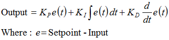
This leads pretty much everyone to write the following PID controller:
/*working variables*/
unsigned long lastTime;
double Input, Output, Setpoint;
double errSum, lastErr;
double kp, ki, kd;
void Compute()
{
/*How long since we last calculated*/
unsigned long now = millis();
double timeChange = (double)(now - lastTime);

/*Compute all the working error variables*/
double error = Setpoint - Input;
errSum += (error * timeChange);
double dErr = (error - lastErr) / timeChange;

/*Compute PID Output*/
Output = kp * error + ki * errSum + kd * dErr;

/*Remember some variables for next time*/
lastErr = error;
lastTime = now;
}

void SetTunings(double Kp, double Ki, double Kd)
{
kp = Kp;
ki = Ki;
kd = Kd;
}
Compute() is called either regularly or irregularly, and it works pretty well. This series isn’t about “works pretty well” though. If we’re going to turn this code into something on par with industrial PID controllers, we’ll have to address a few things:
- Sample Time – The PID algorithm functions best if it is evaluated at a regular interval. If the algorithm is aware of this interval, we can also simplify some of the internal math.
- Derivative Kick – Not the biggest deal, but easy to get rid of, so we’re going to do just that.
- On-The-Fly Tuning Changes – A good PID algorithm is one where tuning parameters can be changed without jolting the internal workings.
- Reset Windup Mitigation –We’ll go into what Reset Windup is, and implement a solution with side benefits
- On/Off (Auto/Manual) – In most applications, there is a desire to sometimes turn off the PID controller and adjust the output by hand, without the controller interfering
- Initialization – When the controller first turns on, we want a “bumpless transfer.” That is, we don’t want the output to suddenly jerk to some new value
- Controller Direction – This last one isn’t a change in the name of robustness per se. it’s designed to ensure that the user enters tuning parameters with the correct sign.
- NEW: Proportional on Measurement – Adding this feature makes it easier to control certain types of processes
Once we’ve addressed all these issues, we’ll have a solid PID algorithm. We’ll also, not coincidentally, have the code that’s being used in the lastest version of the Arduino PID Library. So whether you’re trying to write your own algorithm, or trying to understand what’s going on inside the PID library, I hope this helps you out. Let’s get started.
Next >>
UPDATE: In all the code examples I’m using doubles. On the Arduino, a double is the same as a float (single precision.) True double precision is WAY overkill for PID. If the language you’re using does true double precision, I’d recommend changing all doubles to floats.

@akshay this output can be passed to PWM logic. on the arduino however, the PWM is too fast for a triac (assuming 60hz mains,) so you need to write your own code that implements a slower version of PWM: http://arduino.cc/playground/Code/PIDLibraryRelayOutputExample
hi, is the code above in this website (under beginner’s PID) a code for arduino I can use for PID controller for DC motor. Basically I’m trying to get PID values of a spinning DC motor and I’m using IR sensor to get the rpm of the DC motor… whenever I put my finger on the DC motor, the rpm values will change thus allowing to get outputs of PID values to control the DC motor. so is this the code that allows me to do that?
@ven you CAN use this code, but as I explain it has some deficiencies. if you use the Arduino PID Library you will get a more robust controller.
it seems like my comment did not go through this website. I wanted to ask few questions… well more like I have a problem here. I tried to use your code to print out the PID when I apply physical interruption on DC motor (severe change of rpm) but it seems like I”m not getting any PID values. How can I be able to solve this? I went to arduino library website and used some of basic output examples with still no results. Is there a way for me to send you my current code so that you can take a look at it to see what I’m doing wrong?
sir,
you said that the PID output can be passed to the PWM logic. but can u please tell me what happens in the PWM logic . is it so that the PID value is multiplied with the duty cycle of the PWM. please explain . i just want to know how the PID output reduces or increases the PWM pulse width.
Hi Brett,
Without exagerating, I think this is one of the best blog articles I have ever read. It has shown me more about PID control than any robotics book with all of its theory has shown me.
Thank you for all of your help!!!!
Very nice tutorial, thanks so much! Is there any chance for a pdf version?
BR,
Greg
Hey Brett, great work with the library. It makes control system setups much faster.
How does the library deal with output scaling? By this I mean taking a large error (for a motor, say 1000 RPM, because it is just starting up) and scale it to fit an output of 0-255 (Arduino analog out)? Clearly 0-1000 is larger than 0-255 I’m just wondering how that works.
go on like this such that everyone knows whats happening in library so that customization can be done using basic concept.