
In conjunction with the release of the new Arduino PID Library I’ve decided to release this series of posts. The last library, while solid, didn’t really come with any code explanation. This time around the plan is to explain in great detail why the code is the way it is. I’m hoping this will be of use to two groups of people:
- People directly interested in what’s going on inside the Arduino PID library will get a detailed explanation.
- Anyone writing their own PID algorithm can take a look at how I did things and borrow whatever they like.
It’s going to be a tough slog, but I think I found a not-too-painful way to explain my code. I’m going to start with what I call “The Beginner’s PID.” I’ll then improve it step-by-step until we’re left with an efficient, robust pid algorithm.
The Beginner’s PID
Here’s the PID equation as everyone first learns it:
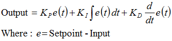
This leads pretty much everyone to write the following PID controller:
/*working variables*/
unsigned long lastTime;
double Input, Output, Setpoint;
double errSum, lastErr;
double kp, ki, kd;
void Compute()
{
/*How long since we last calculated*/
unsigned long now = millis();
double timeChange = (double)(now - lastTime);

/*Compute all the working error variables*/
double error = Setpoint - Input;
errSum += (error * timeChange);
double dErr = (error - lastErr) / timeChange;

/*Compute PID Output*/
Output = kp * error + ki * errSum + kd * dErr;

/*Remember some variables for next time*/
lastErr = error;
lastTime = now;
}

void SetTunings(double Kp, double Ki, double Kd)
{
kp = Kp;
ki = Ki;
kd = Kd;
}
Compute() is called either regularly or irregularly, and it works pretty well. This series isn’t about “works pretty well” though. If we’re going to turn this code into something on par with industrial PID controllers, we’ll have to address a few things:
- Sample Time – The PID algorithm functions best if it is evaluated at a regular interval. If the algorithm is aware of this interval, we can also simplify some of the internal math.
- Derivative Kick – Not the biggest deal, but easy to get rid of, so we’re going to do just that.
- On-The-Fly Tuning Changes – A good PID algorithm is one where tuning parameters can be changed without jolting the internal workings.
- Reset Windup Mitigation –We’ll go into what Reset Windup is, and implement a solution with side benefits
- On/Off (Auto/Manual) – In most applications, there is a desire to sometimes turn off the PID controller and adjust the output by hand, without the controller interfering
- Initialization – When the controller first turns on, we want a “bumpless transfer.” That is, we don’t want the output to suddenly jerk to some new value
- Controller Direction – This last one isn’t a change in the name of robustness per se. it’s designed to ensure that the user enters tuning parameters with the correct sign.
- NEW: Proportional on Measurement – Adding this feature makes it easier to control certain types of processes
Once we’ve addressed all these issues, we’ll have a solid PID algorithm. We’ll also, not coincidentally, have the code that’s being used in the lastest version of the Arduino PID Library. So whether you’re trying to write your own algorithm, or trying to understand what’s going on inside the PID library, I hope this helps you out. Let’s get started.
Next >>
UPDATE: In all the code examples I’m using doubles. On the Arduino, a double is the same as a float (single precision.) True double precision is WAY overkill for PID. If the language you’re using does true double precision, I’d recommend changing all doubles to floats.

Hello Brett,
I have been searching a lot for PID basics and how to code it. This is the best material I have discovered.I am doing a project on speed control of DC motor.
Now I want to following your instructions here on the page and want to see myself why I need the improvements that you have suggested.I will post the feedback on my way.thanks
Aha!! my PID seems working now..Lot of things start making sense.
One quick thought here and I would expect feedback from the author that the- errSum should be “static double” not just “static”
otherwise everytime u call the function the variable errSum would have destroyed its previous value.
thanks
Anil
Anil, What programming language are you using? generally declaring errSum at the class level (the way it’s written above) makes the value persist in the way you are describing.
Pingback: Mini Ultra 8 MHz – Current Consumption (Part 2) |
Brett,
Fantastic description, 3 weeks ago PID just meant process identifier to me. Now, you’ve opened up a whole new world. Thanks for the clear and insightful definition.
Oh, _raising hand_ .. I have a system which has an very high lag on the input. How would you incorporate high lag?
Regards,
Greg.
Thanks Greg. as far as lag… I guess it depends what you mean by lag. if the process is just slow, then conservative tuning parameters will be all you need. If, on the other hand, you have a process where you change the output, then wait for awhile, then all of a sudden the Input takes off… pid alone may not be enough. You might be able to get away with just using conservative tunings, but this is where things like feed forward control come into play. feed forward is outside the scope of this series.
if you’d like to talk specifically about your project, you can shoot me an email. Even better would be to post on the newly created diy-pid-control google group.
This is a great article. I’ve been working on a reflow controller and intended to use time proportional control. I’ve been reviewing your PID RelayOutput example and was wondering if you could explain your example a bit. More specifically, the section where the PID output is used to determine when the relay is turned on or off. I’m not understanding how that portion of the routine is determining on time vs. off time.
Thanks,
Curtis
Thanks Brett, I’ve posted on the site you suggested.
Oh, I just noticed a little bug above – probably just a typo
But, in SetTunings the Kd input parameter is getting assigned to itself…
My assumption is you wanted to have
kd = Kd not Kd=Kd
Regards,
Greg
Thanks Greg! It’s been fixed.
very good!
Pingback: Demystifying PID Control with a look at the new Arduino PID library - Hack a Day
Thanks for an excellent article. By far the best PID material I’ve ever read.
Thanks very much for the work on the library, and even more for the explanation & documentation.
I am wanting to build a kiln controller, where I will need to ramp the temperature up from 150C to 700C over 5 hours, then keep it at 700 for 2 hours (plus a few more steps, but you get the picture).
Thanks to your work I think I understand how to implement the keep stable part of the process, but I am not sure about the ramping up temperature. Is it as simple as calculating that at T+10mins I need to be at say 160C, T+20 170C etc and then plugging the new temperature values in to the PID function? This feels wrong, but I am not sure why.
I would appreciate any assistance you are able to give me (including what I am trying to do is actually called).
Pat
pat, it feels so wrong but it’s oh so right.
What you’re referring to is called Setpoint Ramping, and it’s done all the time in industry. Just compute a new setpoint every minute, or every 10 seconds, whatever. The PID will follow, trying to make the temperature equal to the setpoint you gave it. over at rocketscream they used this aproach to get a sexy reflow curve
as a side note. feel free to join the diy pid control google group. it’s a little more conducive to Q&A.
Very nice lib !
But if you do he math from the laplace form to the iteration one, you will see that the Integral term should be calculated with the PREVIOUS errorSum.
You should add the error to the errorSum AFTER you compute the output.
@jojo interesting. I’m a weird controls engineer in that I don’t really do much work in the laplace domain (perish the thought.) it might be interesting to pit the two methods against each other to see the difference
Thanks, I will check out the google group.
You, sir, are a gentleman and a complete badass.
I wrote a PID algorithm last year for a hotplate I built, and ran into every single one of these problems. I solved a few of them, but you covered solutions to all of them here in incredible detail.
Thank you!!
@Andrew YOU sir, win the make me laugh comment award. I only wish I had done this a year ago so I could have saved you some trouble.
@jojo I was intrigued by your suggestion and did a few tests. I’ve posted the results here
Hi Brett, excellent article!
However, can you provide an example of what setpoint/input and output could mean. I am having quite a hard time following the graphs without some actual units/numerical values.
Take temperature for example, would the variable Input be the ADC result from sampling the sensor? Do we then compute in terms of voltages or temperature?
What would the Output be then? Some values to control the PWM or DAC??
What units would that be in?
@jason I toyed around with putting units on the graphs but ultimately decided against it. One of the beauties of PID is that it’s so general. The setpoint, input, and output can be any type analog signal (provided the setpoint and input are on the same scale) Using a thermocouple input as an example. You could feed the raw chip output into the PID Input, OR you could calculate the actual temperature value and feed THAT into the PID. both would work. You’d need different tuning parameters because the magnitudes would be different, but you could get the same performance from either.
On the output side you are correct. The pid sends out an analog value which in most cases you must convert to the largely digital language of microprocessors. This can be a PWM, DAC, or if PWM is too fast for you (if you’re using a relay or SSR,) you can compute something like “Relay On Time” for a given window.
If you have a specific application in mind, I recommend posting to the diy-pid-control google group. We can flesh things out there.
Would love to see someone doing a similar on a AVR mcu using C (gcc).
Hello Brett!
Excellent job! In my project PID library works almost fine! But i have one problem: when my Setpoint = 0 and Input > 0 then Output is > 0, but when Input < 0 then Output is always = 0. I need it to work in both directions. Please help me!
@Luqasek
You need to use the SetOutputLimits function. By default the library Output is limited to 0-255 (Arduino PWM limits.) Using SetOutputLimits you can change the limits to whatever you like
Thank you very much! It was so simple! I do not know why I had not thought about that before:) Now my project works almost fine! I have to try miscellaneous settings of Kp Ki and Kd. Studies taught us about the selection of the optimal PID controller settings, but it’s not that easy and I do not know how I would do it. I remember a little method called Ziegler–Nichols. Do you have any tips for me? Thanks again!
I’ve been looking for this and can’t thank you enough. Your code will be used in my Quadcopter for stabilization. Thank you so much for publishing this.
sir/mam,
i am working on project temperature controller using PID algorithm. sir in my project i am clear with the hardware, but m getting struck in the programming part.
i am supposed to give the output of this pid algorithm to the DAC which will pass it’s signals to the fan or heater depending upon the present temperature .
i am confused as in how will this output Output = kp * error + ki * errSum + kd * dErr; will go to DAC .
pls help
regards n thanks in advance
ginny 🙂
The Output value will need to be written directly to the DAC. How to do that is outside my experience, and outside the scope of this post. I would suggest searching for: “how to write a float (or double) to DAC” then use that information to send the value of Output.
Hey Brett,
Thank you for your nice explanation and documentation of your code. It really helped clear out a lot of things.
I am only wondering why at the end of your code, you defined the PID parameters as: kp=KP, ki=Ki, kd=Kd? What is the use behind it although we have kp, ki, kd as the parameters in the output equation.
Thanks
Engineer.
Hi Brett,
Thank you so much for your nice explanation, I have cleared in my understand PID controller implement.
Thanks again.
Mr.P
Hello.
It is a wonderful tutorial. However, I have a question.
I am working to build (as many others) a sous vide machine.
The heating element of the water is an immersion heater, you just plug it to the wall power jack. In this case, I will connect it with a SSR (Solid State Relay). The power in Greece, is 220 Volts, 50 Hz, so, a full period is 20 mseconds.
When I want to reduce the temperature of the water, I will not allow the power to be transfered to my heater for the full period (I will control the SSR with a microcontroller). When I want to raise the temperature, I will allow the power to be transfered to my heater for a bigger amount of time than before.
The problem is that there is not a standard way to determine the output of the temperature when the immersion heaters are ON for the full period. It largely depents on the volume of the liquid and on many other factors.
So, how will I translate the output of the PID to a time between 0 and 20 mseconds?
I am afraid that I didn’t make my question clear. Please ask what you did not understand.
Thanks,
Bill.
Hi Bill, take a look at the Relay output example included with the arduino pid library. that should give you the code you need to convert the analog output into a pulse duration.
Thanks for the quick answer.
I think I understand now but I am still a bit confused. I will go over your tutorial once more and if I have questions I will ask again.
But I think that I won’t have problems.
Thanks again,
Bill.
Hello again. I am back with more questions!
Two things I don’t understand from the previous example.
1. The choice of the 5000 is random. How is this selected? I mean, I have a couple of ideas, but they all include experimentation.
2. The system seems to be working relative with the current PWM. How will I set the first value when it starts? Again, experiments to determine which is the best value?
Also, my PWM will be from 0 to 20 mseconds, so it is quite fast. My immersion heater is not scaled and I don’t know of a proper way to scale it myself. Again, I can play with experiments. But, what if I want to produce many of them? I cannot play with every one of my machines. I need a standard way.
For example, if my heater is powerful and I set the mid value… in the middle, let’s say from the 256 steps total, I will have it in 128, it may be too strong for my purposes, how will the PID compensate for that? Is’t this going to be way to complicated? Like working in another control system, far more difficult than PID?
I hope my question is clear now.
Thanks again,
Bill.
Notation nit-picking:
“Where e = Setpoint – Input” should instead be “Where: Error(t) = Setpoint – Input(t)”
The notation “e(t)” hasn’t been pre-defined, and is unnecessary in any case.
It should be made clear that the input depends on time, but the Setpoint doesn’t. Well, Setpoint can depend on time, but it is pre-programmed, unlike the input.
– Doc Pedant
Hey Brett or anybody !
Have you guys been doing some PID-Tn controllers ? My idea would be to discretize the ODE with Euler but I am not sure if that would be the best idea.
Maybe somebody can recommend some good literature ?
Greets !
@Stefan, I’ve only ever done this once, and when I did I used the method you describe.
Ok thanks ! I’ll probably do it with c2d() in matlab – seems to be working fine enough – altough its everything else but elegant ; )
Great, Hope Continue such sort of work dude.
Thanks,but i guess that your program is not suitable for use in the computer programing.In your program,it calculate the time between now and last time we run the program;but we usually call the program periodically instead of calculating the time .
@bennyhuang I’m confused. did you look at that’s the fist issue I address. This page is “the beginner’s pid” I make many improvements over the course of the series.
Hey Brett,
This is a very good article and covering exactly what I was looking for. I am building a PID temperature control system with Arduino, but am interested in learning how the sketch works. The input for this system is temperature (obviously) and the output is fan speed, but I was wondering what this compute() function actually outputs to the pins on Arduino. I assume it is just a voltage, but I am wondering how the system is able to convert a temperature reading to a voltage. Also, I am using PWM to control the fans which take 12V, if that matters.
@Ryan, strictly speaking, both the input to and output from the pid are numbers (the output is limit to 0-255 by default.) how these numbers get to/from the pid are unknown to it. the most likely setup for your system would be:
Input = analogRead(inputPin); //this converts 0-5V on the pin into an int between 0-1023
pid.Compute();
analogWrite(outputPin, Output); //this takes the output from the pid (0-255) and converts it to a 5V pwm signal.
this is the simplest setup. if you wanted to convert the input value to the actual temperature (or something else) before feeding it into the pid that’s fine, just be advised that the optimal values of kp, ki, and kd will be different then the non-converted system.
hi, thanks for the article!!
the first time i understand how to use the [t] in such formulas.
1.can you explain more the way you convert the output to on/off relay?
2.there is a way to look inside the function like “SetOutputLimits()”?
I’m using c and c++ so i have to convert the code.
thanks alot,
David
correction ; I’m using c and NOT C++
hi ,
thanks for your article.
i have 2 questions , can you explain if you call the compute() every x time or it’s ruining all time?
and about the time var. , this var become zero and start all over again, how do you prevent “now – last_time” become negative?
thanks
david
I’m told by my professor that if I put my finger on the spinning DC motor, and the value of rpm changes then I should have the microcontroller (Arduino Uno) to apply PID to readjust the rpm back to its normal regular speed…
For example…
Like let’s say the rpm of a motor goes to 12000 rpm and then I add my finger to the dc motor and it reads 8000 rpm and so my professor told me to have PID applied so that even if I put my finger into the dc motor, the PID will take care and have the dc motor go back to original 12000 rpm.
how would I make this to be?
I wrote a pseudocode below to show what I mean…
if interruption on spinning dc motor occurs
then calculate PID on rpm
how would I make this happen?
thanks.
@ven actually, that pseudo-code should happen when you’re designing the system. if the motor isn’t strong enough to handle the load of your finger, then you should set up your system to continuously use PID. most of the time it won’t be doing much (“everything’s fine, keep the output constant”) but when someone applies a finger it will automatically respond and increase power to the motor.
i do understand a bit, but i have a few questions.
lets take temperature control for example where a situation arises to keep the temperature constant. a heating coil is used which is controlled by a TRIAC. if the set point is 200 and input is 198. then error is 2. then the output is calculated by the formula Output = kp * error + ki * errSum + kd * dErr. but how is the output given to the TRIAC. i mean in what form. how is this done.