Archive for the ‘Projects’ Category

DIY Safety Razor Handle

Saturday, March 6th, 2010

DIY Safety Razor

It’s terrifying.  I’m still in shock that it actually works, but it totally does. One dollar of materials and two or three hours of work, and I now have a safety razor of my very own.

Why? Why would you do something like this?

Basically, I’m cheap and I like making things for myself. I’d been toying with the idea off-and-on since reading a Lifehacker post on safety razors. It all came together for me this past week.

Eureka!

dimension extraction

I was looking at an image from an old razor patent when inspiration struck. Based on the known razor width and some trigonometry, I was able to determine that the two main radii were 0.53″ and 0.66″. It turns out that these are almost identical to 3/4″ and 1″ sch40 pvc, which is available everywhere.

Construction

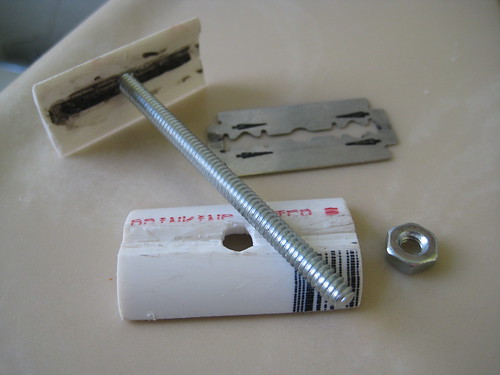
Disassembled

Sorry. No mid-build pictures on this project. I never thought it would work. This was supposed to be a study of sorts, just seeing how things might work in further iterations. Instead it worked, and I’m stuck trying to give the gist of it…

  1. Cut a piece of 3/4″ pvc slightly bigger than the desired top piece.
  2. Wrap sandpaper around some 1″ pvc and sand down the botton edge of the 3/4″.
  3. Cut a section of 1″ pvc for the bottom piece.
  4. Make holes in the top and bottom pieces.
  5. Run a bead of jbweld down the center of the top piece.  as it hardens shape it into a ridge.
  6. After the jb hardens, sand such that it just fits the blade’s slot.
  7. Remove material from the bottom piece to make room for the jb ridge.
  8. In theory, you’re done!  In reality there’s some fine-tuning to do.  It took me about an hour of trial-and-error sanding until I was happy with the final shape of the top piece.

I’m going to shave with this for awhile, and when I make the next one I’ll try to be more diligent about documentation.

flattr this!

OpenSCAD: A Love Story

Friday, November 27th, 2009

Ok, maybe that’s a bit strong, but I’d definitely say we’re dating. I heard about OpenSCAD from the Make Blog, and with a belly fully of thanksgiving turkey I tried it out. I agree with the Make post and the referenced Thingiverse post : In the right hands, designing the right parts, this is a game changer. I played around with it for maybe 3 hours, and was able to generate this:

burr plate

Insane. I’ve been toying with the idea of making a grist mill using burr plates. The main hurdle for me was visualizing all the different angles and how they would interact. I tried drawing one in SketchUp, but after many hours, I threw in the towel. Before OpenSCAD came along I was trying to build the mental momentum to draw the plate in Processing! Seriously. I was going to use their 3D libraries and a TON of math so I could play with a parametrized model.

burr plate code

Speaking of coding, I should also mention that the code to generate the model is TINY. I’ve spread it out and commented it here, but in rough-and-dirty form, the code is less than 10 lines. 10 LINES! I’m free to edit any of the parameters, re-render, and a new model pops right up. Great stuff.

So I’d say there’s a new tool in the tool-box. It’s by no means the only one I’ll use, but certain modeling tasks just got a heck of a lot easier.

flattr this!

REALLY deconstructing a Doodle Pro

Wednesday, November 25th, 2009

I didn’t really “deconstruct” the doodle pro in the last post. I split the housing apart with a screwdriver, and I didn’t even show pictures! What a gyp. For those of you that are interested in a little more, here you go:

Doodle Pro - Layers Separated

I pulled apart the drawing panel. It looks like it’s made up of two sheets of plastic. One is embossed with a honeycomb, and the other is then fused over-top. I really had to yank to get these apart, so I’m guessing they used some heat to melt them together.

Inside there’s metal shavings and a PUTRID smelling liquid. You know how cherry, watermelon, orange, etc flavors don’t taste like the real thing? Imagine if the same people were asked to make something that smells like feet. That’s the best analogy I can think of: synthetic feet smell.

Oh man, if you could…

Now the million dollar question… could someone DIY one of these? Maybe using a clear plastic mesh and two thin sheets of the same plastic? I think the hardest part would be dealing with the liquid. It needs to be viscous enough to hold the shavings in place, it needs to be opaque, and the plastic layers need to be fused closed with the liquid in place.

If you could make one in the 3′ x 4′ range, the payoff would be huge. Even if you don’t do what I’m thinking with it, it would still make a kick-ass whiteboard replacement.

flattr this!

Deconstructing a Doodle Pro (a.k.a Magna Doodle)

Wednesday, November 18th, 2009

I’ve been really intrigued by various Etch-A-Sketch automation projects out there (here’s a few.) I’m excited by the prospect of a large, diy, low energy display. I’d love to use one to make a web-synced wall calendar. I can see two major hurdles in the The Etch-A-Sketch route though: You can’t lift the pen, and you need to shake it (or redistribute the powder somehow,) to erase the drawing.

Doodle Pro

I went around and around in my head, trying to figure out how to overcome these issues, when my girlfriend says, “Why not use a Magna Doodle?” Why not indeed! The erasing process is just a swipe of a magnet, and there’s no aluminum dust to contend with. Much easier. (I should mention here that while I have always known this toy as “Magna Doodle,” that’s a discontinued name. Fisher Price bought it and renamed it “Doodle Pro.”)

There’s a wrinkle though. Unlike the Etch-A-Sketch, the Doodle Pro needs the pen to be on the viewer’s side of the screen. That would probably be ok, but ideally I’d like all the display hardware to be hidden from view. What to do, what to to?

Doodle Pro Test - FrontDoodle Pro Test - Back

Well, I got some cheap Doodle Pros today, and upon taking one apart, it looks like that may not be an issue. It turns out that when you draw something on one side, you get a decent negative on the other! So I’m going to try, at least at first, to create a display with the pen hidden from view. The user will see a black (gray, I guess) background with white lines. The lines are a little fatter than I’d like, but there may be some improvements that can be made to the pen that will fix that.

flattr this!

Success!

Saturday, October 10th, 2009

chugging along

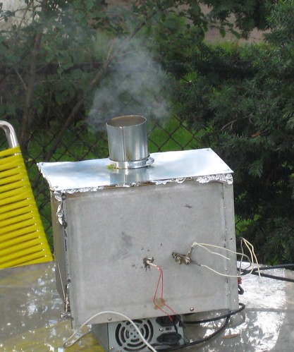
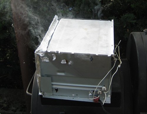
Constant Air + Constant Heat = Constant Smoke. Who knew?

Constant Air

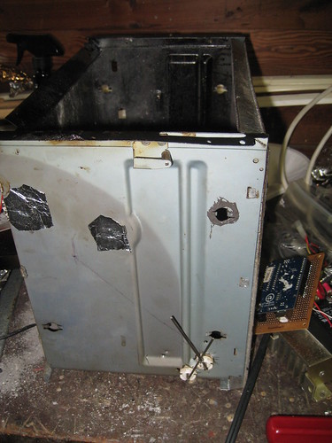
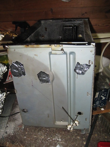
pre-patch JBpost-patch

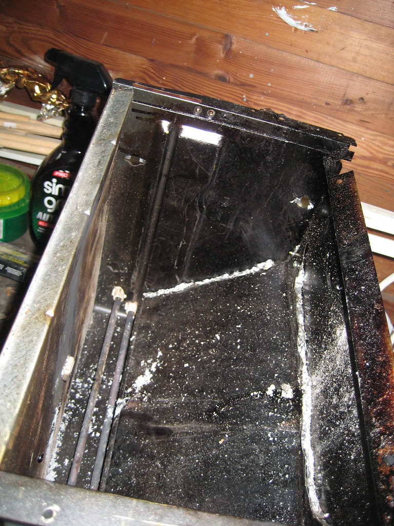
Holes. There were tons of holes. To have complete control over the air I had to patch them all. Most of them were fairly easy. A little JBWeld and aluminum foil and I had rigid, (fairly) high temp patches. All the seams got a bead of JB for good measure as well.

repositioned ramp

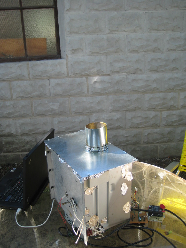
The biggest hole of all was at the front, where the toaster door used to be. The box was essentially open. What I did there was rotate the entire box 90 degrees, making that opening the top. The ramp needed to be repositioned, but that wasn’t too hard. Now the gaping hole was on the exit side of the chamber, where leaks aren’t as important.

The cover for this hole was also upgraded. Where before it was covered using a big piece of foil, I finally used something better: a nice metal sheet with a 3″ outlet pipe.

Constant Heat

thermistorThermistor Location

In the previous attempt I had scrapped the stock themostat and switched to SSR control of the heating elements. I set it to a fixed value, walked away, and the whole thing promptly caught on fire.

This time around, I added a thermistor to the mix. It’s amazing what a little feedback can do. As far the control algorithm, I didn’t bother using the PID library (*gasp*.) For a process this simple all it took was a back-of-the-envelope P-only controller. It held the temperature and SSR output constant, and more importantly, things didn’t catch fire.

Vibration

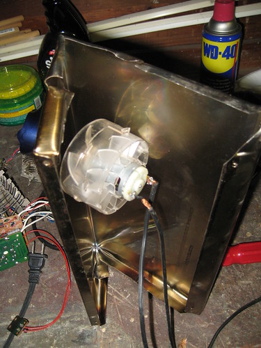
As before, I used a blow-drier fan for vibration. This time, however, it was mounted on the OUTSIDE of the box. It vibrated well -10 seconds every 15 minutes- for the duration of the test. It also didn’t melt into a pile of goo, which was a definite plus.

Results

this is why we're here

I’m ecstatic.   All my success criteria have been met! The Smoke was consistent, and by restricting the air inlet I was able to adjust smoke density.

I put in a pound of wood (3 large chunks), and this thing ran for 5 hours straight before the smoke started to die down. There’s room for 3-4 Times as much wood in there, so an 8-16 hour run time is attainable.

Next Steps

As far as proving out the concept, I’m pretty much done. All that’s left for this phase of the project is to smoke some meat.

Beyond that I’d like to improve the design from a DIY standpoint; making it as easy to copy as possible.

flattr this!

DIY BBQ Smoke Generator – 2nd and 3rd Attempts

Friday, September 25th, 2009

I’ve had a few more gos at making smoke and, well, there’s still work to be done.

2nd Attempt

not bad for 3 bucks

There were two main issues with the first attempt. The smoke was intermittent, and I needed to manually shake the ramp. In the second attempt I tried to take care of both problems with one stroke.  I mounted a fan to the underside of the ramp. This would induce air circulation, and the spinning would vibrate the ramp. I settled on the fan out of a a hair-drier. The idea was appealing for several reasons:

  • An old hair drier is $3 at the thrift store.
  • A hair drier uses 120V AC.  I wouldn’t need a separate source to power it
  • It’s a fan.

Fan mounted to ramp

So I got the fan out and mounted it to the ramp.  It turns out that this idea wasn’t all that good.

  1. Mounting the fan in the middle of the ramp like that did little to improve circulation.
  2. The fan didn’t vibrate all that much
  3. It turns out the motor was actually DC.  They use the heater coil as a resistor to get the voltage they need, then rectify it with a diode.  It’s a brilliant, low cost solution for them.  It was a pain in the butt for me.
  4. The fan was LOUD.  You know, like a hair drier.

So other than learning how a hair drier is wiried, attempt 2 was pretty much a bust. I got the same smoke performance from a louder unit that needed a 12V power supply.

3rd Attempt

The fan didn’t really do much in the second attempt. It didn’t vibrate, and didn’t improve airflow. In the 3rd attempt I tried to fix both problems.

To increase the fan’s vibration, I decided to give it a little off-center weight. Inserting a screw into one of the blades shifted the center of gravity, and made it vibrate like a champ.  This didn’t do anything to help the noise / circulation issues though.  I try to be nice to my neighbors whenever I can, and 4-5 hours of vibrating hair drier noise just isn’t nice.

So I shifted gears. Instead of a constantly vibrating fan with on-off heat, I decided on an intermittent vibrating fan with more consistent heat. Since the initial smoke issues were caused by the On-Off heat control, maybe a more constant heat would lead to constant airflow / smoke. The Fan was relegated to vibration duty, turning on periodically to help the wood settle.

Shield

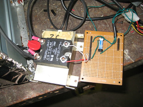
I built an arduino sheild (yes I used an offset header) to:

  • Send a 25% output to an SSR controlling the heaters. 
  • Vibrate the fan for 5sec every 10 min (more than enough to help the wood settle)

Great plan right?  I got everything set up, saw the smoke start, and walked away for 30 min.  Anyone know what happened next?  Anyone?  Yes.  You in the back.  The heaters added more and more heat to the chamber?  More than the air could remove,  even though the airflow was increasing with temperature?  You’re right!  I had suspected that this might happen, just not so quickly. 

…I came back to a fire.  It was contained within the box, and the box was alone on an a stone patio.  There wasn’t any danger, but the fan was cooked.  damn. Here’s some carnage photos where you can see the vibration screw:

Aftermath

Screw

So What Now?

I was hoping to be able to macgyver my way through this thing using aluminum foil and tape.  I’m going to have to up my game a bit.  In future attempts I’m going to start from overkill and work my way down, rather than the bottom up method I’ve been using.   So that means:

  • Really sealing the chamber.
  • Using an external fan
  • Using dampers to control airflow in and out.
  • Mounting the vibration mechanism OUTSIDE the fire box so it doesn’t get smoke/fire damage
  • More precise temperature control.  That’s right.  PID control.  I said overkill.  I meant it.

flattr this!

DIY Barbecure Smoke Generator – First Attempt

Thursday, September 10th, 2009

Smoking

Some serious progress has been made. We have smoke! It’s nowhere near done, but the results are encouraging. Here’s what’s been done since the last post.

Toaster Tear-down

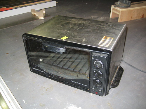
Toaster

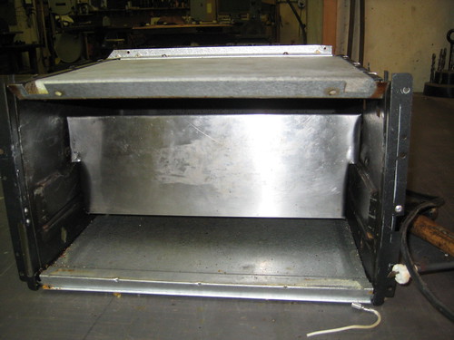
The toaster I used cost me $10 at the thrift store. The first order of business was to take everything apart. 20 minutes with a screwdriver and some wire cutters, and I was left with the components I needed:

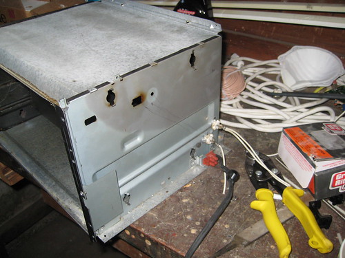
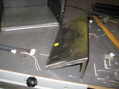
Stripped down

  • A heat-resistant box
  • 2 heating elements
  • A thermostat
  • An extra piece of sheet metal for the ramp (formerly the toaster’s outer shell)

Electronics

All that stuff is in every toaster, and it’s all I really needed. This was a high-end model apparently, so there was a bunch of extra electronic components in there too. Lots of goodies for future projects. I won’t bother listing them all, but take a look at this picture. Not a bad haul for $10!

Heating Element Relocation

Relocated Heaters

With everything apart, I could start construction. Per the design, the heating elements were relocated to the bottom corner of the chamber. I needed new holes, and as you can see from the picture, I did a terrible job. I should’ve used a sheet-metal drill. Instead I used tin-snips. Oh well. The holes are in the right place, and the heating elements fit.

Ramp Construction

Fabbed RampRamp Inserted

The sheet metal that used to form the oven’s outer shell was cut and bent to form the wood-feed ramp. The inner walls of the box are contoured, so it took several tries to get something that fit nicely.

Thermostat Relocation

Relocated Thermostat

The last thing to do was move the thermostat. Since all the heat was going to be localized in a new place, I figured the thermostat should be nearer to it. I made a new hole in the center of the back, and mounted it there.

Time to Test!

Wood

Other than worrying about electrocution and burns, the testing phase was pretty straight forward:

  • I put 3 pieces of apple wood on the ramp so they were touching the heater.
  • Most of the holes in the hot boxwere then sealed with aluminum foil. I left holes for air intake and exhaust.
  • After plugging it in, it took maybe 10 minutes to find the right thermostat setting. I slowly upped the temperature until there was a constant flow of smoke.
  • Beyond that it was just sitting around and basking in the smokey aroma.

Results

Smoking

Of course there’s lots of work still to be done, but I’m really happy with this first attempt.

The Positive:

  • Those 3 pieces of applewood gave me 5 hours of smoke. I only had to intervene twice; shaking the box a little to get the wood to the heaters. Other than that it was continuous, automatic smoke!

Room for improvement:

  • The smoke density wasn’t constant at all.  When the heaters were on there was a lot more smoke formation (Heat + increased convective airflow.) When they we off the smoke tapered off.
  • Needing to manually shake the ramp violates one of the main design criteria I’m shooting for. This thing should “operate unattended.”
  • Currently the thermostat is out in the open, making it susceptible to ambient temperature changes.
  • It’s a little dangerous.  There’s exposed 120VAC all over the place.

flattr this!

DIY Barbecue Smoke Generator – Project Kickoff

Tuesday, September 8th, 2009

Smoke Gen

Unlike most of the projects I’ve done in the past, this one is going to be a multi-poster. There’s just too many ins, too many outs. What’s the project? Turn a toaster oven into a high-quality barbecue smoke generator. Aaaaaand go!

First of All, Why Bother?

I’ll concede there’s a certain Zen-like satisfaction that comes from using only fire.  Constantly tending and tweaking,  making sure everything’s right.  I’ve done that, and with some success.  what I want now though, is consistency.  I want to start the process knowing there aren’t going to be any headaches.  I want automation.  It’s a travesty I know, but I’ve come to terms with that.

Design Criteria

Here’s what I’m going for. If I can get the smoker generator to do the following, I’ll consider the project a complete success. It should:

  • Operate Unattended for 8-16 hours.
  • Generate consistent smoke.
  • Allow for adjustable smoke density
  • Accept standard wood.  (No custom bricks, no sawdust, etc…)

Easy right?

The Plan

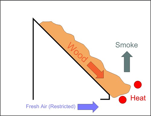
Smoke Gen Principle

The design I’m going to try is pretty similar to what you’d see in a commercial smoker. The wood is on a ramp that leads to a heating element. A restricted amount of air is allowed to flow past the wood. Because there’s incomplete combustion, lots of smoke is generated. As wood is consumed, ash falls away and new wood takes its place. Gravity may be all I need for that to occur, but I’m guessing I’ll need to vibrate the ramp.

Stay Tuned…

It’ll be interesting to see how it goes. Subsequent posts will detail the construction process, as well as testing and any re-design. If it all fails in a huge ball of fire? Well that will be covered as well.
flattr this!

Anatomy of a Digital Thermometer Probe

Sunday, September 6th, 2009

After years of faithful service, the probe on my kitchen thermometer was starting to fail. I have a spare, so the failing one went in a drawer. The other day I was thinking about making my own temperature probe for another project, and figured now would be a perfect time to cut open that old probe to see what’s inside!

Components

Probe Internals

I took the probe down to the ‘ol hackerspace and gave it quick cut on the bandsaw. With the outer sheath open everything just slid out, and I got a look at the internals:

  • Thermistor
  • plastic sheath
  • shielded/insulated single conductor wire

Shielded Single conductor

That last one threw me for a loop.  A SINGLE conductor wire?  I thought for sure there would be two insulated conductors inside that shielding.   It turns out they actually use the shielding as one of the conductors.  In the picture below you can see where the negative lead (I presume) is attached to the shield.

Thermistor Closeup

So there you have it.   Current travels out through the insulated wire, and returns through the shield.  The resistance of the loop is determined by the temperature the thermistor is seeing. The base unit infers the temperature and displays it.

You Mentioned “Another Project?”

Oh right, this is a project blog. The idea for a probe project is this: I make barbecue. During the ~16 hour cooking process I’d like to have 4-5 probes in the meat at various depths. In this way I could show the temperature gradient throughout the cooking process. If I make my own, the probes would be cheap enough to make this project feasible.

flattr this!

Custom HDTV Mount

Tuesday, August 25th, 2009

Mount

Having a hackerspace has totally changed the way I look at the world. I just moved into a new place, and the best place to mount the tv is in a weird corner. Before hackerspace: “ugh. Where else can it go.  $200 for a swivel mount is way too expensive!”  After hackerspace: “$30 in steel and a welder. This is going to be AWESOME!”

Design

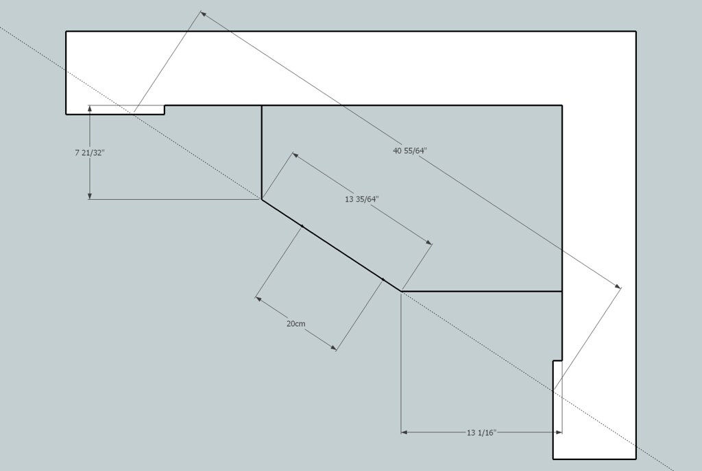
tvmount design

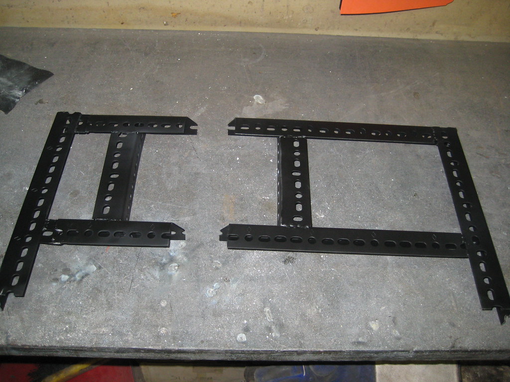
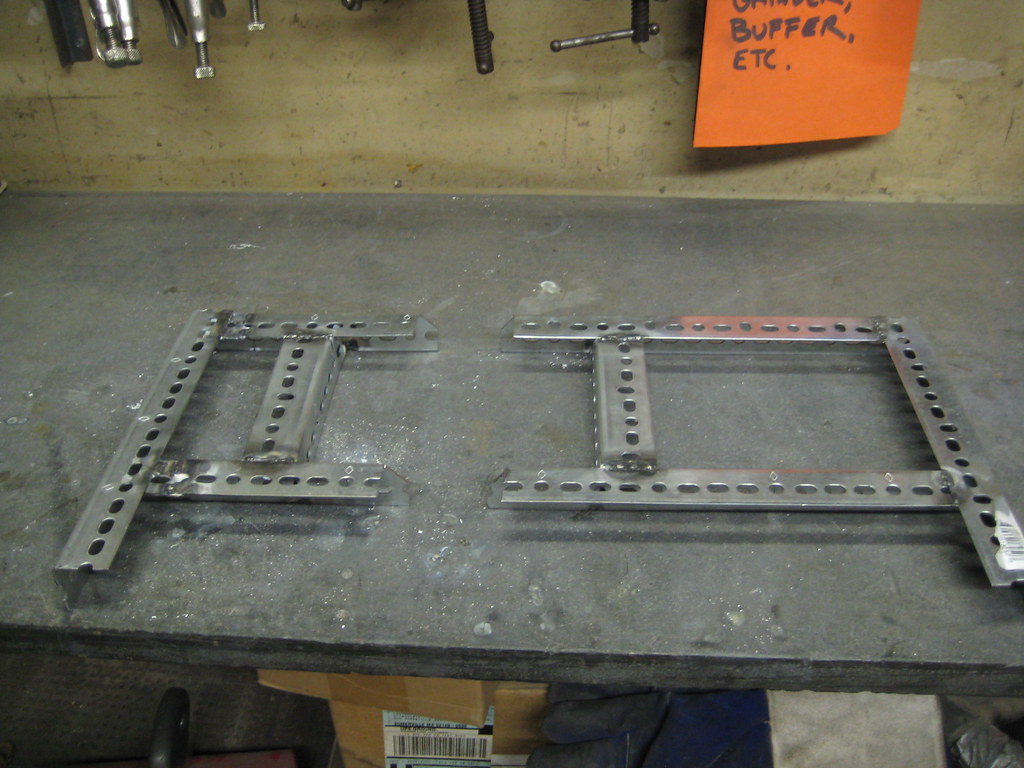
Originally the plan was to weld one solid mount, but when it comes to welding, and construction in general, things don’t always go according to plan. I went the safe route and used a sectional design: two arms lag-screwed to the studs, with cross runners bolted between them.

Construction

weldedpaintedmocked-up

Construction was pretty straight-forward:

  • Cut the steel to length with a bandsaw.
  • Use a milling machine to cut slots for extra adjustability. (Oh. Did I mention we have a milling machine?)
  • Weld it together
  • Paint it (to hide my ugly welds)

Mounting

L-Brackets on TVMount SlotsTV Attached

The Mounting procedure was pretty easy as well:

  • Do some pull-ups on the mount to make sure it will hold the weight
  • Mount slotted, slightly bent, L-brackets to the TV
  • Bolt TV to the mount
  • Make left-right, tilt adjustments
  • Tighten everything down

And that’s it.  I’m really proud of it.  Mostly I’m proud of the fact that my TV hasn’t fallen in the middle of the night.  Materials cost wound up being $40. 1.25″ slotted angle, 4 L-brackets, and a can of spraypaint. I probably could have done it for far less if I had used found materials instead of going to Home Depot.

flattr this!