Archive for the ‘Mechanical’ Category

Anatomy of a Digital Thermometer Probe

Sunday, September 6th, 2009

After years of faithful service, the probe on my kitchen thermometer was starting to fail. I have a spare, so the failing one went in a drawer. The other day I was thinking about making my own temperature probe for another project, and figured now would be a perfect time to cut open that old probe to see what’s inside!

Components

Probe Internals

I took the probe down to the ‘ol hackerspace and gave it quick cut on the bandsaw. With the outer sheath open everything just slid out, and I got a look at the internals:

  • Thermistor
  • plastic sheath
  • shielded/insulated single conductor wire

Shielded Single conductor

That last one threw me for a loop.  A SINGLE conductor wire?  I thought for sure there would be two insulated conductors inside that shielding.   It turns out they actually use the shielding as one of the conductors.  In the picture below you can see where the negative lead (I presume) is attached to the shield.

Thermistor Closeup

So there you have it.   Current travels out through the insulated wire, and returns through the shield.  The resistance of the loop is determined by the temperature the thermistor is seeing. The base unit infers the temperature and displays it.

You Mentioned “Another Project?”

Oh right, this is a project blog. The idea for a probe project is this: I make barbecue. During the ~16 hour cooking process I’d like to have 4-5 probes in the meat at various depths. In this way I could show the temperature gradient throughout the cooking process. If I make my own, the probes would be cheap enough to make this project feasible.

flattr this!

Custom HDTV Mount

Tuesday, August 25th, 2009

Mount

Having a hackerspace has totally changed the way I look at the world. I just moved into a new place, and the best place to mount the tv is in a weird corner. Before hackerspace: “ugh. Where else can it go.  $200 for a swivel mount is way too expensive!”  After hackerspace: “$30 in steel and a welder. This is going to be AWESOME!”

Design

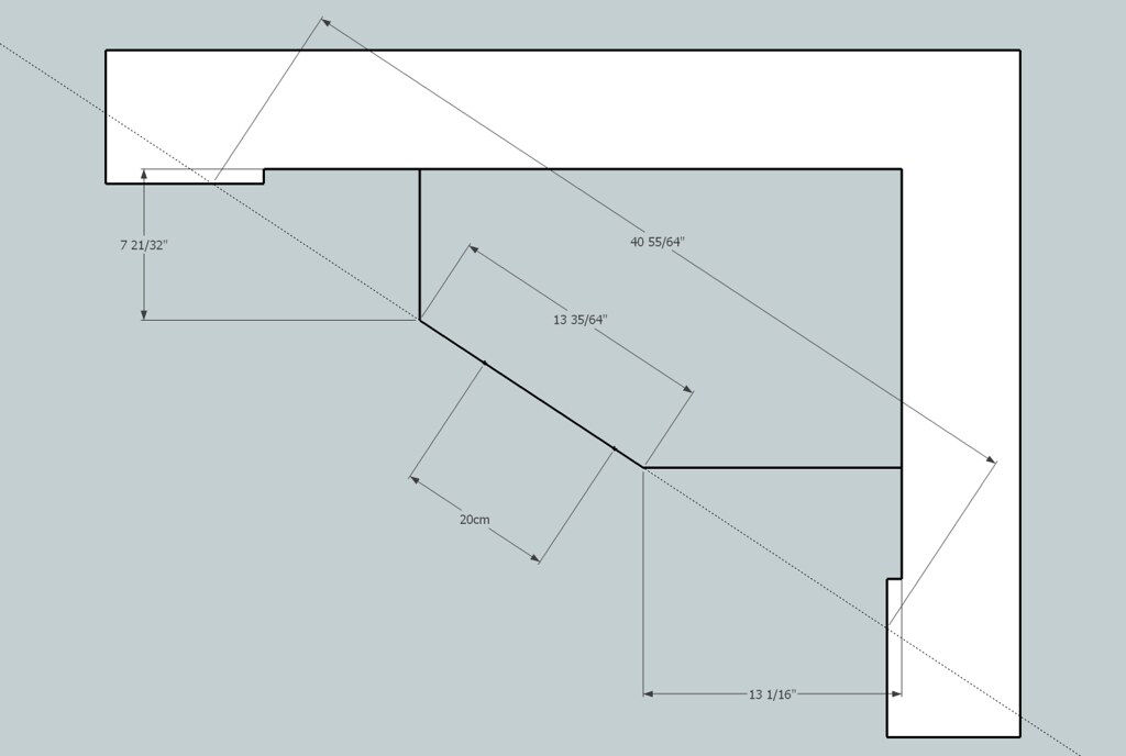
tvmount design

Originally the plan was to weld one solid mount, but when it comes to welding, and construction in general, things don’t always go according to plan. I went the safe route and used a sectional design: two arms lag-screwed to the studs, with cross runners bolted between them.

Construction

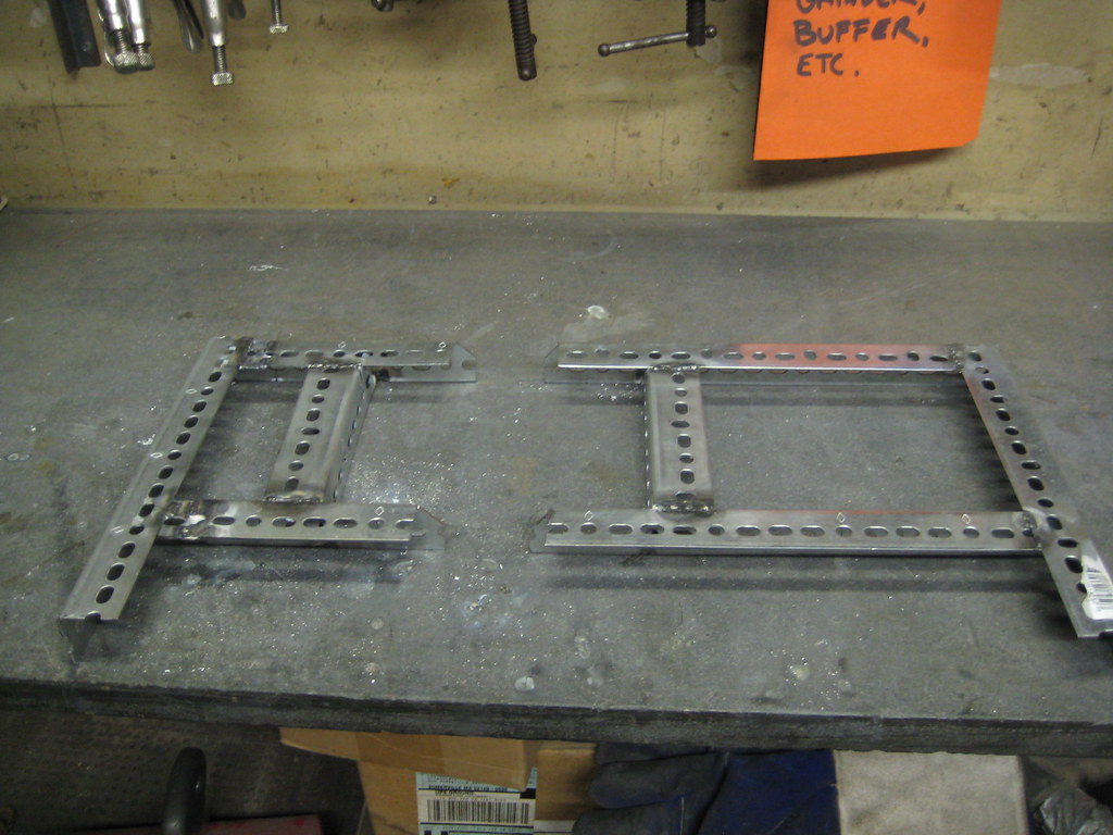
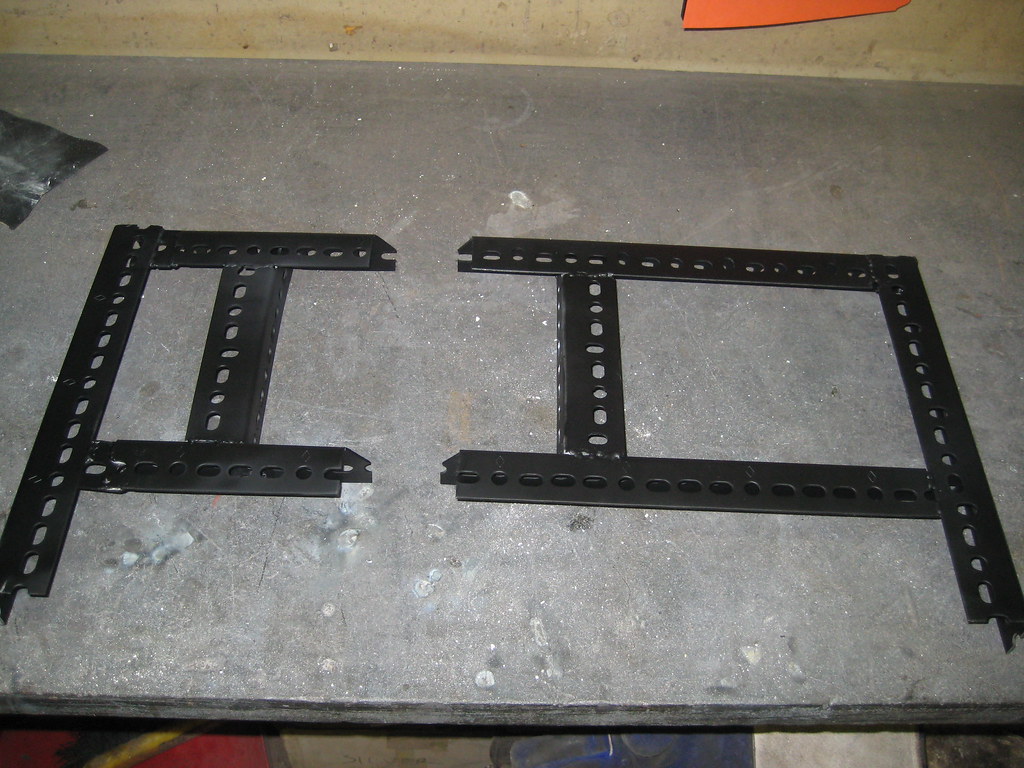
weldedpaintedmocked-up

Construction was pretty straight-forward:

  • Cut the steel to length with a bandsaw.
  • Use a milling machine to cut slots for extra adjustability. (Oh. Did I mention we have a milling machine?)
  • Weld it together
  • Paint it (to hide my ugly welds)

Mounting

L-Brackets on TVMount SlotsTV Attached

The Mounting procedure was pretty easy as well:

  • Do some pull-ups on the mount to make sure it will hold the weight
  • Mount slotted, slightly bent, L-brackets to the TV
  • Bolt TV to the mount
  • Make left-right, tilt adjustments
  • Tighten everything down

And that’s it.  I’m really proud of it.  Mostly I’m proud of the fact that my TV hasn’t fallen in the middle of the night.  Materials cost wound up being $40. 1.25″ slotted angle, 4 L-brackets, and a can of spraypaint. I probably could have done it for far less if I had used found materials instead of going to Home Depot.

flattr this!

DIY Bicycle GPS Mount – Done

Thursday, August 20th, 2009

Mounted and Ready

Look at that sexy GPS Mount! I don’t know how it could have turned out better. In addition to figuring out how to attach it to the bike, there’s a nice coat of tool-dip sprayed on there. It’s an extra layer of scratch insurance, and it makes the mount blend in with the frame. Good stuff all around. Too bad I can’t take credit for any of it. Nice work Will!

Mount side-view

The main issue from the last post was trying to figure out how to get the holder on the bike. Looks like the old-reflector-mount path worked well.

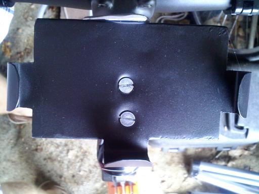
Flush Mount Screws

lock-nuts

The holder is attached to the reflector mount using flushed screws and lock nuts, and mounted to the bike under the headset cap. I totally thought he was going to mount it on the handlebars, but I think this works better. It’s centrally located, and away from the hands.

flattr this!

DIY Bicycle GPS Mount – Take 1

Monday, August 17th, 2009

Locked_And_Loaded

A friend of mine came up for the weekend, and he had an idea for a GPS mount for his bike. We fleshed it out a bit, and came up with this. It’s made from sheet metal scavenged from an old toaster oven.

Insertion_Extraction

The GPS is held really snugly on all 4 sides. The top tongue is held in place by friction, and swings out of the way for easy insertion and removal.

Back_View

There’s one issue that hasn’t been completey ironed out yet. looking at the bottom of this thing, you have to ask, “How does it attach to the bike?” Don’t know yet. We didn’t have one handy, but most ideas revolved around using the mount from an old reflector; either JBWelding it straight to the bottom, or somehow using the bolt. Not sure yet. Once it gets painted / mounted I’ll post some more pictures.

DIY

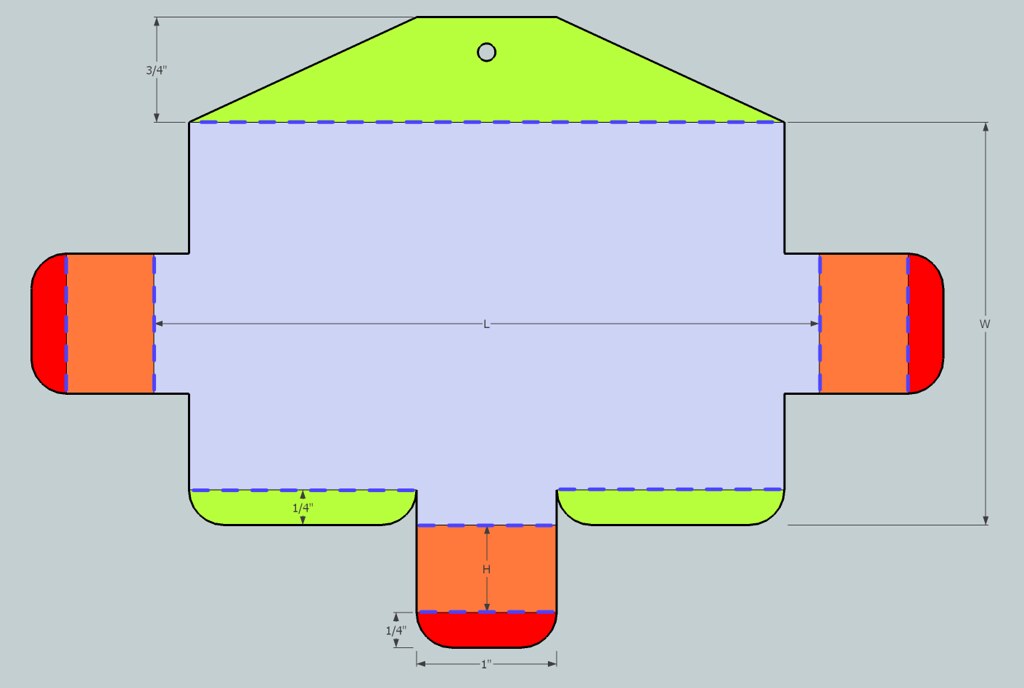
We made this thing for a Garmin Nuvi, but this could be resized for any GPS. Or even – gasp – for the iPhone. Just cut the above shape out of sheet metal, substituting your device’s length width and height into “L”, “W”, and “H”. Bend along the dotted lines, with the yellow doing down, and the orange going up and over. (Click the image for a larger size.)

MAKE SURE to file down & sand all rough edges. if you do this, your device should remain unscratched. If you don’t… not so much.

flattr this!

A Robot that makes things!

Wednesday, June 24th, 2009

There was an immense amount of work that went into getting to this point, and I can only stake claim to a tiny portion of it. It was really cool to see our Makerbot throwing down the plastic… on the 20-30th try.

There were two main wrinkles. One we fixed, the other we lived with.

  • Getting the plastic to stick to the foam-core was hit or miss.  Covering the foam-core with double-sided tape created a much better surface.  We printed out 4 sets of tweezers without replacing the tape!
  • The issue we lived with was the extruder.  It’s not quite gripping the welding rod correctly yet, so we had to apply downward pressure manually. not that big of a deal for a 9 minute print, but it needs to be fixed before we print 4 shot-glasses on the same raft.  Man, if only most of us were members of a kickass hackerspace with access to machine tools.  Oh wait… we are.  Cool!

The other area just begging for improvement is the temperature control. Because the makerbot is using simple on-off control, we’re getting temperature swings of +/- 10 °C. The plan is to put in some data logging to see how bad the problem is, then implement progressively more complicated control strategies until we’re happy with it.

flattr this!

Arduino Reflow Toaster

Sunday, June 14th, 2009

Reflow
Pic 1: Arduino Controlled Toaster-Oven. No, I have not tried making toast with it

The Mark 1 reflow toaster is complete! (“Mark 1” is another way of saying there’s a lot of work to be done.)

It can hold +/- 1 °F, which should be sufficient for surface mount electronics. I say “should be” because I haven’t soldered anything with it yet.

Construction:
Reflow-Mast
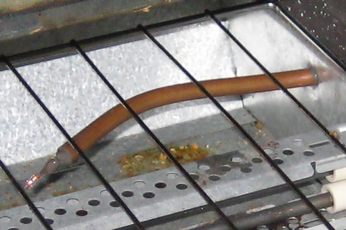
Pic 2: Termistor support mast

Temperature sensing is done by a thermistor. Simple solder connections and 20ga wire get the signal back to the Arduino. (UPDATE: the thermistor is wired at the Arduino using this method.) The wires are run through a copper tube, and everything is held in place with JB weld. This setup seems to work, even at temperatures that melt solder. I don’t know if that’s because the JB keeps the solder connections from melting, or if it holds the molten solder in place during run-time. Either way, I haven’t had any problems getting temperature readings.

On the heat side, an SSR is spliced directly into the 120V plug wire. This is not safe. The SSR is fine, but having exposed 120V dangling near the toaster is a recipe for bad times. In the mark 2 that will all be neatly enclosed.

The toaster’s intrinsic temperature control was left in place, turned all the way up to 500°F.  If everything is working correctly, it will stay out of the way.  If something goes wrong, the temperature will be prevented from rising without bound.

Temperature Control:

I decided to use the Arduino PID Library to control the oven temperature. I think it works really well, but I’m a little biased.
Reflow_OnOff_vs_PID
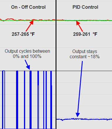
Pic 3: Temperature control: On-Off vs PID. On-Off is easier, while PID provides tighter control with a more stable output

The easiest way to control temperature would be to use on-off control: “If I’m too cold, turn on. if I’m too hot, turn off.” I tried that first. As you can see in the picture above, it does a decent job. The oven temperature (red line) stays within 5 °F of where we want to be (green line.) This is probably fine in this application. The one questionable thing is the output. Since it’s cycling between full on and full off, there might be some extra thermal shock to the system.

On-Off control is probably fine, but as I said, I’m biased. I decided to implement pid control. As you can see, it does a better job of staying where we want to be. Instead of 5 degrees, now the temperature stays within 1 degree. Also, since the output is essentially constant, there’s a better chance that there will be a uniform temperature gradient in the oven.

The extra effort probably wasn’t necessary, but I still think it’s pretty cool.

Next Steps

  • I think the termistor may be in a bad location.  I wanted it to be really close to the workpiece, so I put it directly underneath where the workpiece would go.  it seems that when there’s a piece in place, it actually changes how heat flows in that area, and the temperature reading is almost 20 degrees higher.  I’ll need to see if this adversely impacts reflow…  once I actually reflow something.
  • I may need to upgrade to a convection toaster to get more uniform temperature distribution
  • currently I’m adjusting setpoints and watching progress using the PID frontend.  it would be nice to move that functionality onto the arduino. maybe an LCD and some buttons…
  • It might be cool to have a pre-programmed setpoint profile that the oven can cycle through

flattr this!