Improving the Beginner’s PID – Introduction

April 15th, 2011

In conjunction with the release of the new Arduino PID Library I’ve decided to release this series of posts. The last library, while solid, didn’t really come with any code explanation. This time around the plan is to explain in great detail why the code is the way it is. I’m hoping this will be of use to two groups of people:

  • People directly interested in what’s going on inside the Arduino PID library will get a detailed explanation.
  • Anyone writing their own PID algorithm can take a look at how I did things and borrow whatever they like.

It’s going to be a tough slog, but I think I found a not-too-painful way to explain my code.  I’m going to start with what I call “The Beginner’s PID.”  I’ll then improve it step-by-step until we’re left with an efficient, robust pid algorithm.

The Beginner’s PID

Here’s the PID equation as everyone first learns it:

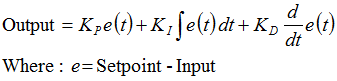
This leads pretty much everyone to write the following PID controller:

/*working variables*/
unsigned long lastTime;
double Input, Output, Setpoint;
double errSum, lastErr;
double kp, ki, kd;
void Compute()
{
   /*How long since we last calculated*/
   unsigned long now = millis();
   double timeChange = (double)(now - lastTime);
 
   /*Compute all the working error variables*/
   double error = Setpoint - Input;
   errSum += (error * timeChange);
   double dErr = (error - lastErr) / timeChange;
 
   /*Compute PID Output*/
   Output = kp * error + ki * errSum + kd * dErr;
 
   /*Remember some variables for next time*/
   lastErr = error;
   lastTime = now;
}
 
void SetTunings(double Kp, double Ki, double Kd)
{
   kp = Kp;
   ki = Ki;
   kd = Kd;
}

Compute() is called either regularly or irregularly, and it works pretty well. This series isn’t about “works pretty well” though. If we’re going to turn this code into something on par with industrial PID controllers, we’ll have to address a few things:

  1. Sample Time – The PID algorithm functions best if it is evaluated at a regular interval. If the algorithm is aware of this interval, we can also simplify some of the internal math.
  2. Derivative Kick – Not the biggest deal, but easy to get rid of, so we’re going to do just that.
  3. On-The-Fly Tuning Changes – A good PID algorithm is one where tuning parameters can be changed without jolting the internal workings.
  4. Reset Windup Mitigation –We’ll go into what Reset Windup is, and implement a solution with side benefits
  5. On/Off (Auto/Manual) – In most applications, there is a desire to sometimes turn off the PID controller and adjust the output by hand, without the controller interfering
  6. Initialization – When the controller first turns on, we want a “bumpless transfer.” That is, we don’t want the output to suddenly jerk to some new value
  7. Controller Direction – This last one isn’t a change in the name of robustness per se. it’s designed to ensure that the user enters tuning parameters with the correct sign.
  8. NEW: Proportional on Measurement – Adding this feature makes it easier to control certain types of processes

Once we’ve addressed all these issues, we’ll have a solid PID algorithm. We’ll also, not coincidentally, have the code that’s being used in the lastest version of the Arduino PID Library. So whether you’re trying to write your own algorithm, or trying to understand what’s going on inside the PID library, I hope this helps you out. Let’s get started.
Next >>

UPDATE: In all the code examples I’m using doubles. On the Arduino, a double is the same as a float (single precision.) True double precision is WAY overkill for PID. If the language you’re using does true double precision, I’d recommend changing all doubles to floats.

Creative Commons License

flattr this!

Arduino Uno Keeps Header Offset

September 27th, 2010

Uno Spacing

The newest version of the arduino was announced last week. At first glance it seemed as though they got rid of the offset header spacing, but a closer look at the spec showed that it is still 0.16 inches. It would have been a bold move to change that spacing; there are a lot of 0.16-spaced shields out there. Looks like Sparkfun will be selling offset headers for some time to come.

See also: Offset Header Explained

flattr this!

This changes everything

August 13th, 2010

A lot of my projects involve 120VAC, switching relatively slowly. Most people use mechanical relays in that situation, but I don’t like them; I try to avoid moving parts whenever possible. Up to this point, I’ve always used solid state relays. They work really well, but they’re expensive. What this means is that I’ve needed to move my same 2 SSRs from project to project, which is kind of a pain.

Well no more! Enter the humble Triac. They’re tiny, cheap, and in my slow switching applications the circuitry isn’t too complicated. That being said, it’s still the most complicated circuit I’ve ever attempted.

triac schematic

I figured a good first application would be a switched outlet. It’s fairly simple, and it’s something that I could use in prototyping later on.

IMG_8431

IMG_8430

And there you have it. A neat little package with two independently controlled power plugs. The best part is the cost. The whole thing cost less then $10! With SSRs it would have been ~$80, and I don’t know if they even would have fit in the box.

Triac Box from br3ttb on Vimeo.

There’s one issue I’m going to need to keep an eye on. Apparently, if a Triac overheats, it tends to fail into the on position. There’s nothing here that detects if this is about to happen, so I’ll have to keep an eye on it for a while to be sure there’s adequate cooling

Update: There is NOT adequate cooling. I did a real test just now. 1500W toaster oven on high. after a minute I started smelling perfboard. Everything was disconnected before any damage was done, but some design revisions are in order before I try to switch high loads again.

flattr this!

PID Library ported to mbed

July 27th, 2010

mbed pid

So the guys over at ARM took the arduino pid library and ported it for use with their mbed platform.  Nice little stroke to the ego there.  That’s not the main reason I’m excited though.   Because they’re a legit company,  they have written documentation.

I’m terrible at documentation.  Commenting my code is hard enough.  Writing clear, concise, well-thought-out help files?  I’m as useless as 1000 drunk monkeys with typewriters.

It’s always been nagging at me that the Arduino PID Library didn’t have a clear help document. Now, indirectly, it does. Since the backend is the same, everything they say about the mbed library works with the Arduino library as well.

flattr this!

DIY Safety Razor Handle

March 6th, 2010

DIY Safety Razor

It’s terrifying.  I’m still in shock that it actually works, but it totally does. One dollar of materials and two or three hours of work, and I now have a safety razor of my very own.

Why? Why would you do something like this?

Basically, I’m cheap and I like making things for myself. I’d been toying with the idea off-and-on since reading a Lifehacker post on safety razors. It all came together for me this past week.

Eureka!

dimension extraction

I was looking at an image from an old razor patent when inspiration struck. Based on the known razor width and some trigonometry, I was able to determine that the two main radii were 0.53″ and 0.66″. It turns out that these are almost identical to 3/4″ and 1″ sch40 pvc, which is available everywhere.

Construction

Disassembled

Sorry. No mid-build pictures on this project. I never thought it would work. This was supposed to be a study of sorts, just seeing how things might work in further iterations. Instead it worked, and I’m stuck trying to give the gist of it…

  1. Cut a piece of 3/4″ pvc slightly bigger than the desired top piece.
  2. Wrap sandpaper around some 1″ pvc and sand down the botton edge of the 3/4″.
  3. Cut a section of 1″ pvc for the bottom piece.
  4. Make holes in the top and bottom pieces.
  5. Run a bead of jbweld down the center of the top piece.  as it hardens shape it into a ridge.
  6. After the jb hardens, sand such that it just fits the blade’s slot.
  7. Remove material from the bottom piece to make room for the jb ridge.
  8. In theory, you’re done!  In reality there’s some fine-tuning to do.  It took me about an hour of trial-and-error sanding until I was happy with the final shape of the top piece.

I’m going to shave with this for awhile, and when I make the next one I’ll try to be more diligent about documentation.

flattr this!

OpenSCAD: A Love Story

November 27th, 2009

Ok, maybe that’s a bit strong, but I’d definitely say we’re dating. I heard about OpenSCAD from the Make Blog, and with a belly fully of thanksgiving turkey I tried it out. I agree with the Make post and the referenced Thingiverse post : In the right hands, designing the right parts, this is a game changer. I played around with it for maybe 3 hours, and was able to generate this:

burr plate

Insane. I’ve been toying with the idea of making a grist mill using burr plates. The main hurdle for me was visualizing all the different angles and how they would interact. I tried drawing one in SketchUp, but after many hours, I threw in the towel. Before OpenSCAD came along I was trying to build the mental momentum to draw the plate in Processing! Seriously. I was going to use their 3D libraries and a TON of math so I could play with a parametrized model.

burr plate code

Speaking of coding, I should also mention that the code to generate the model is TINY. I’ve spread it out and commented it here, but in rough-and-dirty form, the code is less than 10 lines. 10 LINES! I’m free to edit any of the parameters, re-render, and a new model pops right up. Great stuff.

So I’d say there’s a new tool in the tool-box. It’s by no means the only one I’ll use, but certain modeling tasks just got a heck of a lot easier.

flattr this!

REALLY deconstructing a Doodle Pro

November 25th, 2009

I didn’t really “deconstruct” the doodle pro in the last post. I split the housing apart with a screwdriver, and I didn’t even show pictures! What a gyp. For those of you that are interested in a little more, here you go:

Doodle Pro - Layers Separated

I pulled apart the drawing panel. It looks like it’s made up of two sheets of plastic. One is embossed with a honeycomb, and the other is then fused over-top. I really had to yank to get these apart, so I’m guessing they used some heat to melt them together.

Inside there’s metal shavings and a PUTRID smelling liquid. You know how cherry, watermelon, orange, etc flavors don’t taste like the real thing? Imagine if the same people were asked to make something that smells like feet. That’s the best analogy I can think of: synthetic feet smell.

Oh man, if you could…

Now the million dollar question… could someone DIY one of these? Maybe using a clear plastic mesh and two thin sheets of the same plastic? I think the hardest part would be dealing with the liquid. It needs to be viscous enough to hold the shavings in place, it needs to be opaque, and the plastic layers need to be fused closed with the liquid in place.

If you could make one in the 3′ x 4′ range, the payoff would be huge. Even if you don’t do what I’m thinking with it, it would still make a kick-ass whiteboard replacement.

flattr this!

Deconstructing a Doodle Pro (a.k.a Magna Doodle)

November 18th, 2009

I’ve been really intrigued by various Etch-A-Sketch automation projects out there (here’s a few.) I’m excited by the prospect of a large, diy, low energy display. I’d love to use one to make a web-synced wall calendar. I can see two major hurdles in the The Etch-A-Sketch route though: You can’t lift the pen, and you need to shake it (or redistribute the powder somehow,) to erase the drawing.

Doodle Pro

I went around and around in my head, trying to figure out how to overcome these issues, when my girlfriend says, “Why not use a Magna Doodle?” Why not indeed! The erasing process is just a swipe of a magnet, and there’s no aluminum dust to contend with. Much easier. (I should mention here that while I have always known this toy as “Magna Doodle,” that’s a discontinued name. Fisher Price bought it and renamed it “Doodle Pro.”)

There’s a wrinkle though. Unlike the Etch-A-Sketch, the Doodle Pro needs the pen to be on the viewer’s side of the screen. That would probably be ok, but ideally I’d like all the display hardware to be hidden from view. What to do, what to to?

Doodle Pro Test - FrontDoodle Pro Test - Back

Well, I got some cheap Doodle Pros today, and upon taking one apart, it looks like that may not be an issue. It turns out that when you draw something on one side, you get a decent negative on the other! So I’m going to try, at least at first, to create a display with the pen hidden from view. The user will see a black (gray, I guess) background with white lines. The lines are a little fatter than I’d like, but there may be some improvements that can be made to the pen that will fix that.

flattr this!

Success!

October 10th, 2009

chugging along

Constant Air + Constant Heat = Constant Smoke. Who knew?

Constant Air

pre-patch JBpost-patch

Holes. There were tons of holes. To have complete control over the air I had to patch them all. Most of them were fairly easy. A little JBWeld and aluminum foil and I had rigid, (fairly) high temp patches. All the seams got a bead of JB for good measure as well.

repositioned ramp

The biggest hole of all was at the front, where the toaster door used to be. The box was essentially open. What I did there was rotate the entire box 90 degrees, making that opening the top. The ramp needed to be repositioned, but that wasn’t too hard. Now the gaping hole was on the exit side of the chamber, where leaks aren’t as important.

The cover for this hole was also upgraded. Where before it was covered using a big piece of foil, I finally used something better: a nice metal sheet with a 3″ outlet pipe.

Constant Heat

thermistorThermistor Location

In the previous attempt I had scrapped the stock themostat and switched to SSR control of the heating elements. I set it to a fixed value, walked away, and the whole thing promptly caught on fire.

This time around, I added a thermistor to the mix. It’s amazing what a little feedback can do. As far the control algorithm, I didn’t bother using the PID library (*gasp*.) For a process this simple all it took was a back-of-the-envelope P-only controller. It held the temperature and SSR output constant, and more importantly, things didn’t catch fire.

Vibration

As before, I used a blow-drier fan for vibration. This time, however, it was mounted on the OUTSIDE of the box. It vibrated well -10 seconds every 15 minutes- for the duration of the test. It also didn’t melt into a pile of goo, which was a definite plus.

Results

this is why we're here

I’m ecstatic.   All my success criteria have been met! The Smoke was consistent, and by restricting the air inlet I was able to adjust smoke density.

I put in a pound of wood (3 large chunks), and this thing ran for 5 hours straight before the smoke started to die down. There’s room for 3-4 Times as much wood in there, so an 8-16 hour run time is attainable.

Next Steps

As far as proving out the concept, I’m pretty much done. All that’s left for this phase of the project is to smoke some meat.

Beyond that I’d like to improve the design from a DIY standpoint; making it as easy to copy as possible.

flattr this!

DIY BBQ Smoke Generator – 2nd and 3rd Attempts

September 25th, 2009

I’ve had a few more gos at making smoke and, well, there’s still work to be done.

2nd Attempt

not bad for 3 bucks

There were two main issues with the first attempt. The smoke was intermittent, and I needed to manually shake the ramp. In the second attempt I tried to take care of both problems with one stroke.  I mounted a fan to the underside of the ramp. This would induce air circulation, and the spinning would vibrate the ramp. I settled on the fan out of a a hair-drier. The idea was appealing for several reasons:

  • An old hair drier is $3 at the thrift store.
  • A hair drier uses 120V AC.  I wouldn’t need a separate source to power it
  • It’s a fan.

Fan mounted to ramp

So I got the fan out and mounted it to the ramp.  It turns out that this idea wasn’t all that good.

  1. Mounting the fan in the middle of the ramp like that did little to improve circulation.
  2. The fan didn’t vibrate all that much
  3. It turns out the motor was actually DC.  They use the heater coil as a resistor to get the voltage they need, then rectify it with a diode.  It’s a brilliant, low cost solution for them.  It was a pain in the butt for me.
  4. The fan was LOUD.  You know, like a hair drier.

So other than learning how a hair drier is wiried, attempt 2 was pretty much a bust. I got the same smoke performance from a louder unit that needed a 12V power supply.

3rd Attempt

The fan didn’t really do much in the second attempt. It didn’t vibrate, and didn’t improve airflow. In the 3rd attempt I tried to fix both problems.

To increase the fan’s vibration, I decided to give it a little off-center weight. Inserting a screw into one of the blades shifted the center of gravity, and made it vibrate like a champ.  This didn’t do anything to help the noise / circulation issues though.  I try to be nice to my neighbors whenever I can, and 4-5 hours of vibrating hair drier noise just isn’t nice.

So I shifted gears. Instead of a constantly vibrating fan with on-off heat, I decided on an intermittent vibrating fan with more consistent heat. Since the initial smoke issues were caused by the On-Off heat control, maybe a more constant heat would lead to constant airflow / smoke. The Fan was relegated to vibration duty, turning on periodically to help the wood settle.

Shield

I built an arduino sheild (yes I used an offset header) to:

  • Send a 25% output to an SSR controlling the heaters. 
  • Vibrate the fan for 5sec every 10 min (more than enough to help the wood settle)

Great plan right?  I got everything set up, saw the smoke start, and walked away for 30 min.  Anyone know what happened next?  Anyone?  Yes.  You in the back.  The heaters added more and more heat to the chamber?  More than the air could remove,  even though the airflow was increasing with temperature?  You’re right!  I had suspected that this might happen, just not so quickly. 

…I came back to a fire.  It was contained within the box, and the box was alone on an a stone patio.  There wasn’t any danger, but the fan was cooked.  damn. Here’s some carnage photos where you can see the vibration screw:

Aftermath

Screw

So What Now?

I was hoping to be able to macgyver my way through this thing using aluminum foil and tape.  I’m going to have to up my game a bit.  In future attempts I’m going to start from overkill and work my way down, rather than the bottom up method I’ve been using.   So that means:

  • Really sealing the chamber.
  • Using an external fan
  • Using dampers to control airflow in and out.
  • Mounting the vibration mechanism OUTSIDE the fire box so it doesn’t get smoke/fire damage
  • More precise temperature control.  That’s right.  PID control.  I said overkill.  I meant it.

flattr this!