DIY Barbecure Smoke Generator – First Attempt

September 10th, 2009

Smoking

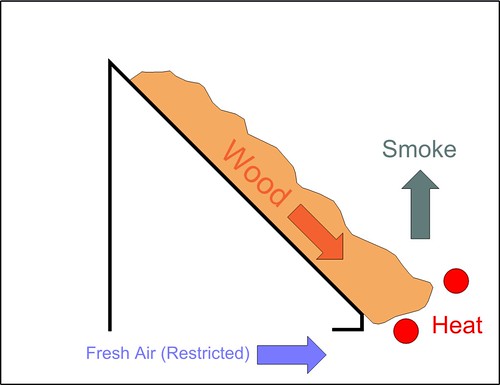
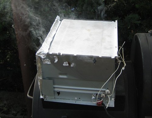
Some serious progress has been made. We have smoke! It’s nowhere near done, but the results are encouraging. Here’s what’s been done since the last post.

Toaster Tear-down

Toaster

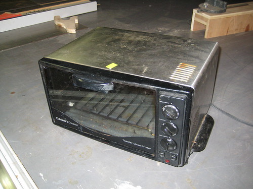
The toaster I used cost me $10 at the thrift store. The first order of business was to take everything apart. 20 minutes with a screwdriver and some wire cutters, and I was left with the components I needed:

Stripped down

  • A heat-resistant box
  • 2 heating elements
  • A thermostat
  • An extra piece of sheet metal for the ramp (formerly the toaster’s outer shell)

Electronics

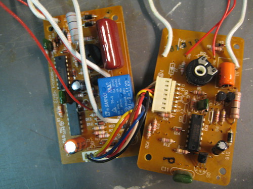
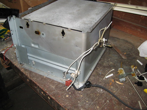
All that stuff is in every toaster, and it’s all I really needed. This was a high-end model apparently, so there was a bunch of extra electronic components in there too. Lots of goodies for future projects. I won’t bother listing them all, but take a look at this picture. Not a bad haul for $10!

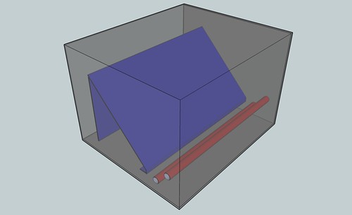
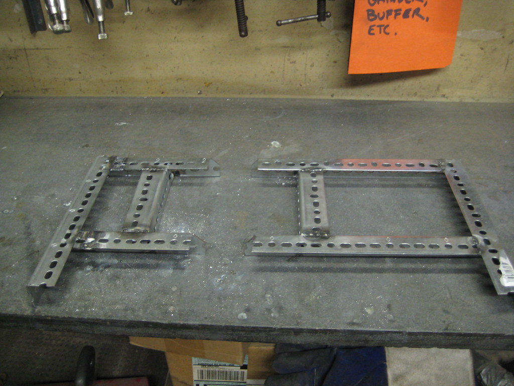
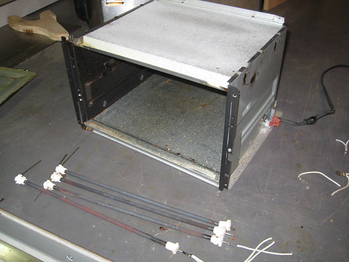
Heating Element Relocation

Relocated Heaters

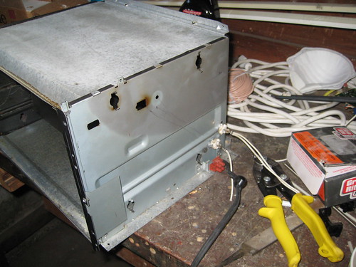
With everything apart, I could start construction. Per the design, the heating elements were relocated to the bottom corner of the chamber. I needed new holes, and as you can see from the picture, I did a terrible job. I should’ve used a sheet-metal drill. Instead I used tin-snips. Oh well. The holes are in the right place, and the heating elements fit.
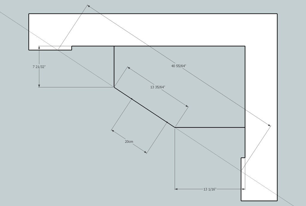
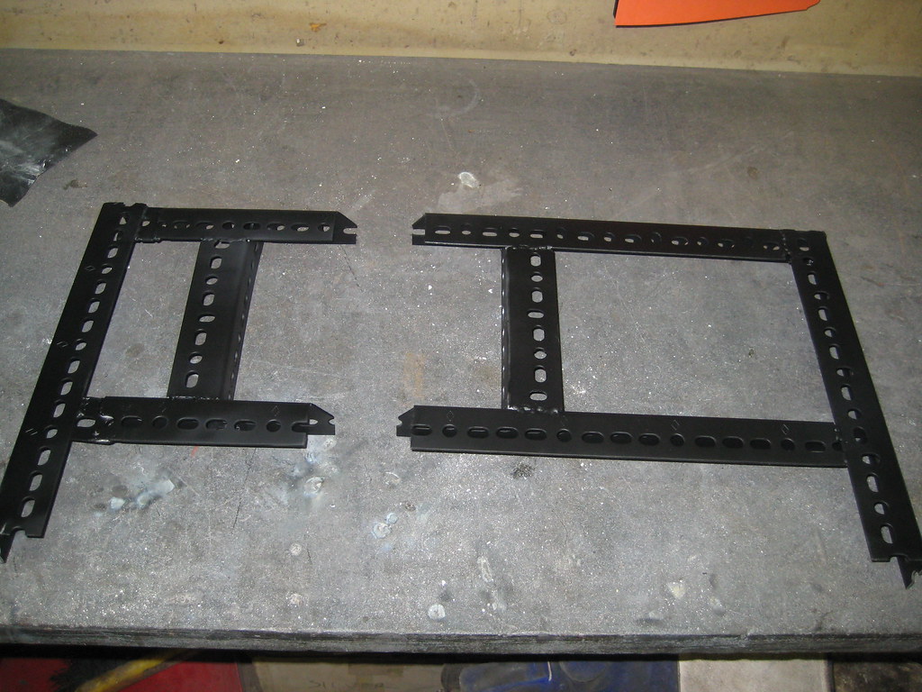
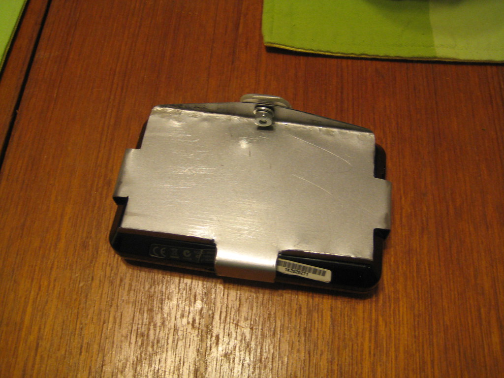
Ramp Construction

Fabbed RampRamp Inserted

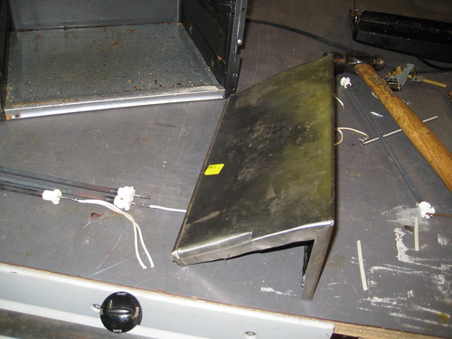
The sheet metal that used to form the oven’s outer shell was cut and bent to form the wood-feed ramp. The inner walls of the box are contoured, so it took several tries to get something that fit nicely.

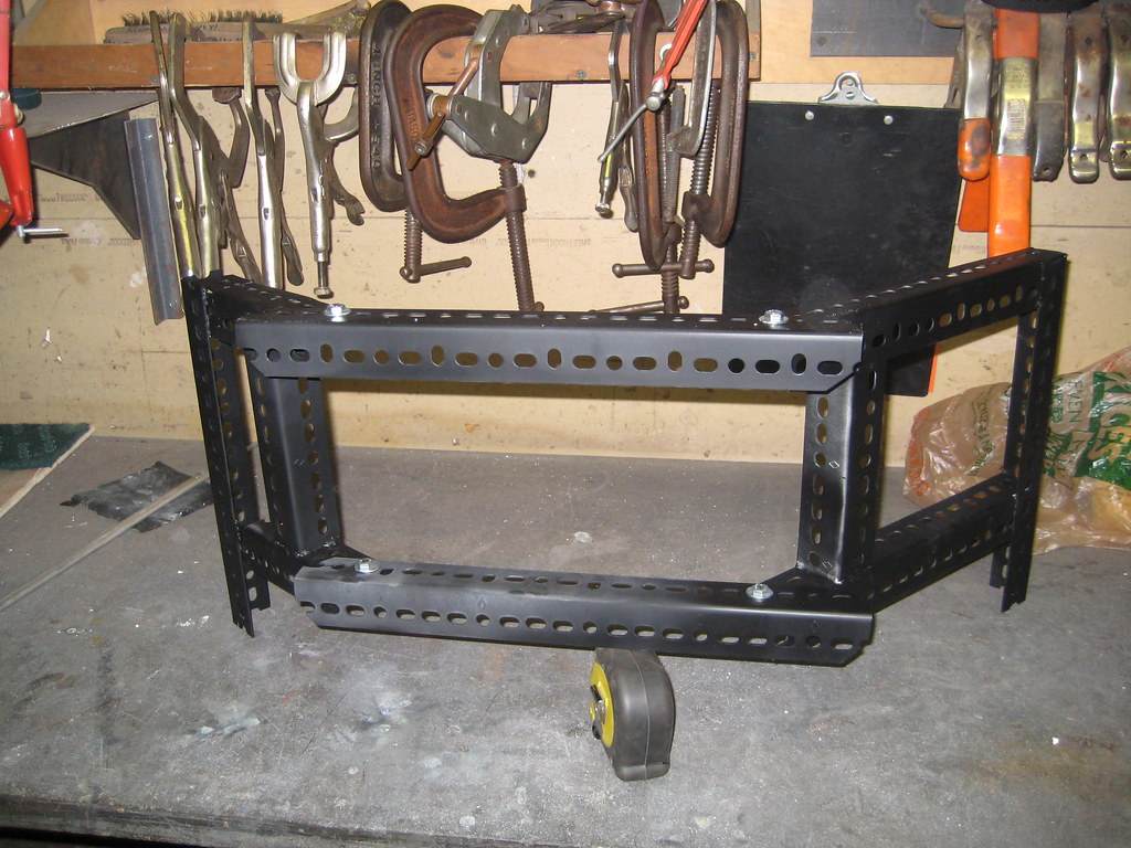
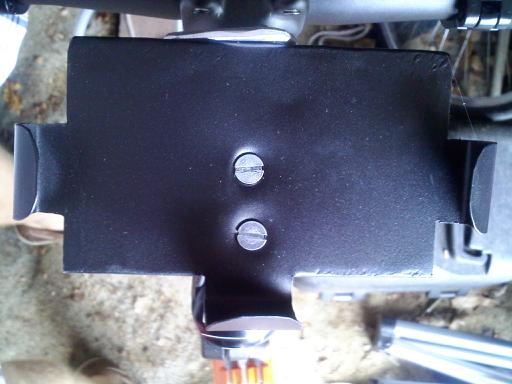
Thermostat Relocation

Relocated Thermostat

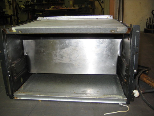
The last thing to do was move the thermostat. Since all the heat was going to be localized in a new place, I figured the thermostat should be nearer to it. I made a new hole in the center of the back, and mounted it there.

Time to Test!

Wood

Other than worrying about electrocution and burns, the testing phase was pretty straight forward:

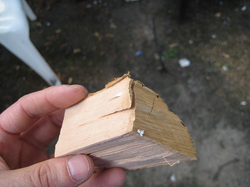
  • I put 3 pieces of apple wood on the ramp so they were touching the heater.
  • Most of the holes in the hot boxwere then sealed with aluminum foil. I left holes for air intake and exhaust.
  • After plugging it in, it took maybe 10 minutes to find the right thermostat setting. I slowly upped the temperature until there was a constant flow of smoke.
  • Beyond that it was just sitting around and basking in the smokey aroma.

Results

Smoking

Of course there’s lots of work still to be done, but I’m really happy with this first attempt.

The Positive:

  • Those 3 pieces of applewood gave me 5 hours of smoke. I only had to intervene twice; shaking the box a little to get the wood to the heaters. Other than that it was continuous, automatic smoke!

Room for improvement:

  • The smoke density wasn’t constant at all.  When the heaters were on there was a lot more smoke formation (Heat + increased convective airflow.) When they we off the smoke tapered off.
  • Needing to manually shake the ramp violates one of the main design criteria I’m shooting for. This thing should “operate unattended.”
  • Currently the thermostat is out in the open, making it susceptible to ambient temperature changes.
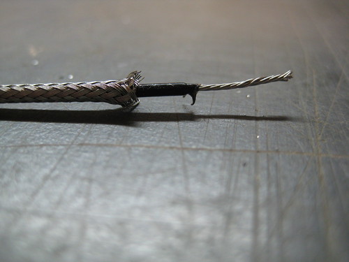
  • It’s a little dangerous.  There’s exposed 120VAC all over the place.

flattr this!

DIY Barbecue Smoke Generator – Project Kickoff

September 8th, 2009

Smoke Gen

Unlike most of the projects I’ve done in the past, this one is going to be a multi-poster. There’s just too many ins, too many outs. What’s the project? Turn a toaster oven into a high-quality barbecue smoke generator. Aaaaaand go!

First of All, Why Bother?

I’ll concede there’s a certain Zen-like satisfaction that comes from using only fire.  Constantly tending and tweaking,  making sure everything’s right.  I’ve done that, and with some success.  what I want now though, is consistency.  I want to start the process knowing there aren’t going to be any headaches.  I want automation.  It’s a travesty I know, but I’ve come to terms with that.

Design Criteria

Here’s what I’m going for. If I can get the smoker generator to do the following, I’ll consider the project a complete success. It should:

  • Operate Unattended for 8-16 hours.
  • Generate consistent smoke.
  • Allow for adjustable smoke density
  • Accept standard wood.  (No custom bricks, no sawdust, etc…)

Easy right?

The Plan

Smoke Gen Principle

The design I’m going to try is pretty similar to what you’d see in a commercial smoker. The wood is on a ramp that leads to a heating element. A restricted amount of air is allowed to flow past the wood. Because there’s incomplete combustion, lots of smoke is generated. As wood is consumed, ash falls away and new wood takes its place. Gravity may be all I need for that to occur, but I’m guessing I’ll need to vibrate the ramp.

Stay Tuned…

It’ll be interesting to see how it goes. Subsequent posts will detail the construction process, as well as testing and any re-design. If it all fails in a huge ball of fire? Well that will be covered as well.

flattr this!

Anatomy of a Digital Thermometer Probe

September 6th, 2009

After years of faithful service, the probe on my kitchen thermometer was starting to fail. I have a spare, so the failing one went in a drawer. The other day I was thinking about making my own temperature probe for another project, and figured now would be a perfect time to cut open that old probe to see what’s inside!

Components

Probe Internals

I took the probe down to the ‘ol hackerspace and gave it quick cut on the bandsaw. With the outer sheath open everything just slid out, and I got a look at the internals:

  • Thermistor
  • plastic sheath
  • shielded/insulated single conductor wire

Shielded Single conductor

That last one threw me for a loop.  A SINGLE conductor wire?  I thought for sure there would be two insulated conductors inside that shielding.   It turns out they actually use the shielding as one of the conductors.  In the picture below you can see where the negative lead (I presume) is attached to the shield.

Thermistor Closeup

So there you have it.   Current travels out through the insulated wire, and returns through the shield.  The resistance of the loop is determined by the temperature the thermistor is seeing. The base unit infers the temperature and displays it.

You Mentioned “Another Project?”

Oh right, this is a project blog. The idea for a probe project is this: I make barbecue. During the ~16 hour cooking process I’d like to have 4-5 probes in the meat at various depths. In this way I could show the temperature gradient throughout the cooking process. If I make my own, the probes would be cheap enough to make this project feasible.

flattr this!

Custom HDTV Mount

August 25th, 2009

Mount

Having a hackerspace has totally changed the way I look at the world. I just moved into a new place, and the best place to mount the tv is in a weird corner. Before hackerspace: “ugh. Where else can it go.  $200 for a swivel mount is way too expensive!”  After hackerspace: “$30 in steel and a welder. This is going to be AWESOME!”

Design

tvmount design

Originally the plan was to weld one solid mount, but when it comes to welding, and construction in general, things don’t always go according to plan. I went the safe route and used a sectional design: two arms lag-screwed to the studs, with cross runners bolted between them.

Construction

weldedpaintedmocked-up

Construction was pretty straight-forward:

  • Cut the steel to length with a bandsaw.
  • Use a milling machine to cut slots for extra adjustability. (Oh. Did I mention we have a milling machine?)
  • Weld it together
  • Paint it (to hide my ugly welds)

Mounting

L-Brackets on TVMount SlotsTV Attached

The Mounting procedure was pretty easy as well:

  • Do some pull-ups on the mount to make sure it will hold the weight
  • Mount slotted, slightly bent, L-brackets to the TV
  • Bolt TV to the mount
  • Make left-right, tilt adjustments
  • Tighten everything down

And that’s it.  I’m really proud of it.  Mostly I’m proud of the fact that my TV hasn’t fallen in the middle of the night.  Materials cost wound up being $40. 1.25″ slotted angle, 4 L-brackets, and a can of spraypaint. I probably could have done it for far less if I had used found materials instead of going to Home Depot.

flattr this!

DIY Bicycle GPS Mount – Done

August 20th, 2009

Mounted and Ready

Look at that sexy GPS Mount! I don’t know how it could have turned out better. In addition to figuring out how to attach it to the bike, there’s a nice coat of tool-dip sprayed on there. It’s an extra layer of scratch insurance, and it makes the mount blend in with the frame. Good stuff all around. Too bad I can’t take credit for any of it. Nice work Will!

Mount side-view

The main issue from the last post was trying to figure out how to get the holder on the bike. Looks like the old-reflector-mount path worked well.

Flush Mount Screws

lock-nuts

The holder is attached to the reflector mount using flushed screws and lock nuts, and mounted to the bike under the headset cap. I totally thought he was going to mount it on the handlebars, but I think this works better. It’s centrally located, and away from the hands.

flattr this!

DIY Bicycle GPS Mount – Take 1

August 17th, 2009

Locked_And_Loaded

A friend of mine came up for the weekend, and he had an idea for a GPS mount for his bike. We fleshed it out a bit, and came up with this. It’s made from sheet metal scavenged from an old toaster oven.

Insertion_Extraction

The GPS is held really snugly on all 4 sides. The top tongue is held in place by friction, and swings out of the way for easy insertion and removal.

Back_View

There’s one issue that hasn’t been completey ironed out yet. looking at the bottom of this thing, you have to ask, “How does it attach to the bike?” Don’t know yet. We didn’t have one handy, but most ideas revolved around using the mount from an old reflector; either JBWelding it straight to the bottom, or somehow using the bolt. Not sure yet. Once it gets painted / mounted I’ll post some more pictures.

DIY

We made this thing for a Garmin Nuvi, but this could be resized for any GPS. Or even – gasp – for the iPhone. Just cut the above shape out of sheet metal, substituting your device’s length width and height into “L”, “W”, and “H”. Bend along the dotted lines, with the yellow doing down, and the orange going up and over. (Click the image for a larger size.)

MAKE SURE to file down & sand all rough edges. if you do this, your device should remain unscratched. If you don’t… not so much.

flattr this!

Sparkfun Now Carrying Offset Headers

August 14th, 2009

SparkfunHeader
The title says it all. Their picture is much nicer than mine too. That quarter or theirs really gets around.

Here’s a direct link to the product page.

flattr this!

Sandal Retread using Fillet ‘o Tire

August 2nd, 2009

Sandals After

I did this once years ago, and it worked really well. Take an old tire, and recycle it to make indestructible shoe soles. Tire tread is designed to handle way more abuse than simple walking can dish out. My current sandals were starting to wear down, and it was time to do it again.

There’s just one issue when using a tire: there’s a steel mesh embedded in the rubber. It rigidly holds a curved shape, which is not what you want. The solution I came up with was to fillet the tire, keeping the tread and leaving the steel behind. Good stuff.

Beyond that it’s a straight-forward process. You remove the old soles and glue the new ones on. The rest of my sandals will fall apart long before the soles do.

I took a bunch of pictures. Should make for a decent Instructable.

flattr this!

Arduino Offset Header

July 16th, 2009

The Arduino has a problem.
dimensions
Not a big problem by any means, but still annoying under certain circumstances. As the story goes, an 11th hour design mistake has left the Arduino community with a header that doesn’t follow standard 0.1″ (2.54mm) spacing.

So what?

misalignment

For the most part, this flaw is completely transparent to the user.  Either they plug wires directly into the header, or use shields that have been designed to mate nicely with it. The problem occurs when trying to create your own shield. When you try to line up a standard perfboard with the Arduino, the header doesn’t match up. This has left the community either buying protoshields or resorting to various other DIY techniques. (here’s two.)

An Easier Solution

Offset Header
offset header - standard shield
Thanks to my hackerspace, I’ve been able to machine a jig to make Offset Headers. In my opinion it’s a great solution to the problem. Slide one through the perfboard (or whatever other 0.1″ spaced board you’re using,) solder in place, and you have an Arduino-spaced shield using a standard-spaced board.

But wait… There’s more

offset header - arduino shield

So that takes care of the cheap-shield issue, but there’s more that this header can do. There are TONS of Arduino-spaced sheilds out there. In my opinion, that’s one of the main things keeping people from developing and buying standard-spaced Arduino clones. Currently, if you make your clone standard-spaced, you’re going to alienate all the existing Arduino shields.  Having these offset headers lets users buy a clone without fear of shield compatibility.

Lastly

Many Headers

So that’s it. Offset headers by the boatload.  Hopefully someone somewhere finds them useful. I’ve sent a preliminary batch over to Adafruit, so they should be available there shortly. 

(UPDATE:  they are now available here)
(UPDATE: SparkFun has them now too.)

flattr this!

PID Front-End v0.2

July 4th, 2009

PID_FrontEnd_v02

Some people spend the 4th of July relaxing with friends, drinking beer, enjoying some good weather. I… updated the pid front-end. I got several requests to add grid lines and axes, and now was the time. For those of you with an image of me in a dank basement coding away, fear not. There was a Hawaiian shirt and a hammock involved.

The picture says it all. The trend lines are a little thicker, and there are now axis labels and grid lines. It’s also worth noting, since it was a pain to code, that the time gridlines and labels scroll, and can be displayed in milliseconds, seconds or minutes.

It can be downloaded here.

flattr this!